The Link Layer and LANs
Introduction
The link layer is responsible for the transfer of datagrams from one node to a physically adjacent node over a direct communication link.
Core Terminology
- Nodes: Any device on the network, including hosts (PCs, phones) and routers.
- Links: The communication channels that connect adjacent nodes. These can be wired (Ethernet), wireless (WiFi), or LANs.
- Frame: The Layer-2 packet. It encapsulates the network-layer datagram.
Data-link layer has the responsibility of transferring datagram from one node to physically adjacent node over a link.
Context and Analogies
- Protocol Variation: A datagram may be transferred by different link protocols over different links in its journey (e.g., WiFi on the first hop, Ethernet on the second).
- Each link protocol provides different services, such that it may or may not provide rdt over link
- Transportation Analogy: Think of a trip from Waterloo to Lausanne:
- Tourist = Datagram.
- Transport Segment = Communication link.
- Transportation Mode (Limo, Plane, Train) = Link-layer protocol.
- Travel Agent = Routing algorithm.
Link Layer Services
The link layer provides several critical functions to ensure data moves reliably between neighbors:
- Framing and Link Access: Encapsulates the datagram into a frame by adding a header and a trailer. It uses "MAC" (Medium Access Control) addresses in these headers to identify the source and destination (these are distinct from IP addresses!).
- Link Access: A shared medium is a single communication channel—like the air in Wi-Fi or a common wire—used by multiple devices simultaneously. Because everyone "talks" on the same path, channel access acts as a traffic controller to prevent collisions, which occur when two devices transmit at once and garble the data. It ensures order by either giving each device a specific turn, a dedicated frequency, or by having them "listen" for silence before speaking.
- Reliable Delivery: Ensures data arrives without errors between adjacent nodes. While often used on high-error links like wireless, it is sometimes skipped on low-error fiber or copper links to reduce overhead.
-
Why both link-level and end-end reliability?
This is a classic "defense in depth" strategy in networking.
If you only had Link-Level, a router crash in the middle of the ocean would lose your data forever and you'd never know. If you only had End-to-End, a slightly static-filled Wi-Fi connection would make your internet feel incredibly slow because every tiny error would require a re-send from the original server thousands of miles away.
Link-Level Reliability (The "Local" Fix)
This happens between two physically connected nodes (e.g., your laptop to your router, or one router to the next via fiber).
- Purpose: To catch and fix errors immediately on a "noisy" or unstable physical wire.
- Mechanism: If a packet is corrupted by electromagnetic interference on a single hop, the receiving node identifies the error and asks for a retransmission right then and there.
- Why we need it: If we only had end-to-end reliability, a single bit error on the first of 20 hops would cause the packet to travel 19 more useless hops before the destination finally realized it was broken. That's a massive waste of bandwidth.
End-to-End Reliability (The "Global" Fix)
This happens only at the edges of the network (the source and the final destination), usually handled by TCP.
- Purpose: To ensure the entire "conversation" is complete and in the right order.
- The "End-to-End Argument": Even if every single link in the chain is 100% perfect, errors can still happen inside the intermediate routers (e.g., a router runs out of memory and drops a packet, or a router has a software bug that corrupts data while moving it from an input port to an output port).
- Why we need it: Only the two endpoints truly know what the complete message is supposed to look like. The intermediate nodes are just passing boxes; they don't care if a packet is missing from a 5GB file download.
- Flow Control: Pacing the sending node so it does not overwhelm the receiving node.
- Error Detection: Identifies errors caused by signal attenuation or noise. The receiver may ask for a retransmission or simply drop the corrupted frame.
- Error Correction: The receiver identifies and fixes bit errors without needing a retransmission.
- Half-Duplex and Full-Duplex: In half-duplex, nodes at both ends can transmit, but not at the same time (like a walkie-talkie).
-
Implementation and Communication
- Location: The link layer is implemented in a Network Interface Card (NIC) or on a dedicated chip (controller). It is a combination of hardware, software, and firmware.
- Hardware Attachment: The NIC attaches to the host's system bus (e.g., PCI) and handles both the link and physical layers.
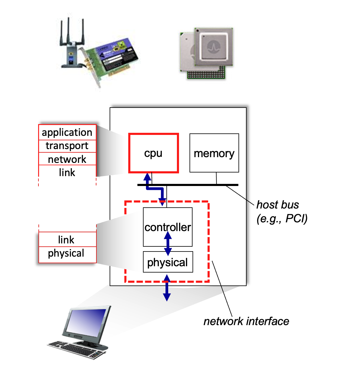
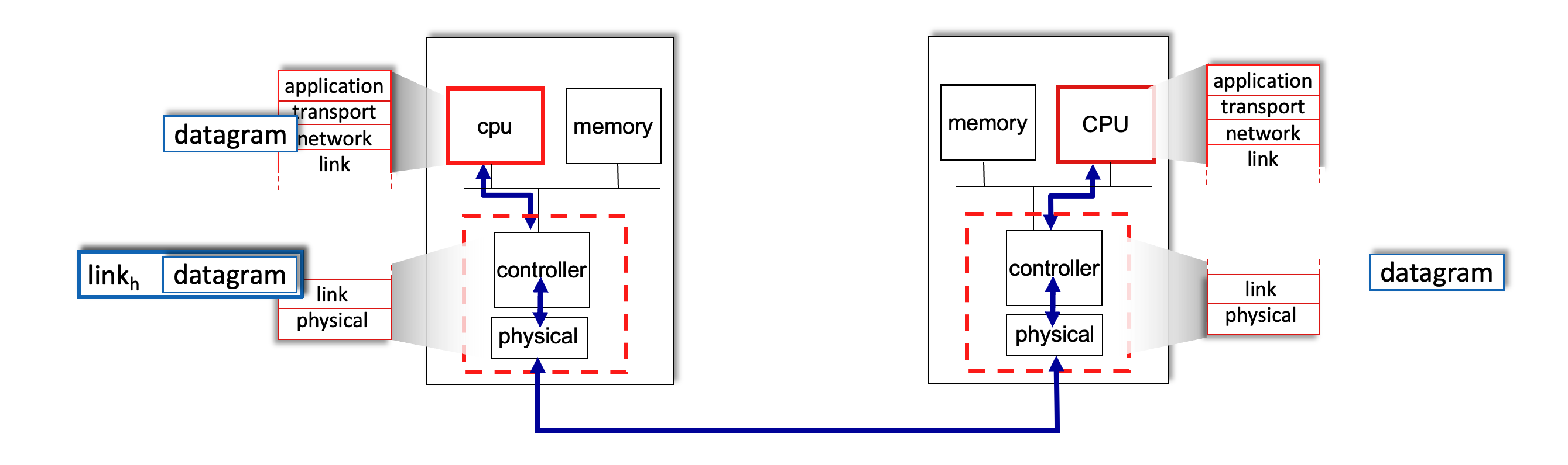
- Interface Communication Process:
- Sending Side: Encapsulates the datagram in a frame, adds error-checking bits, and handles flow control.
- Receiving Side: Looks for errors, extracts the datagram, and passes it up to the network layer.
Multiple Access Protocols
When multiple nodes share a single communication channel, the network layer needs a way to coordinate transmissions to prevent interference.
Two Types of Links
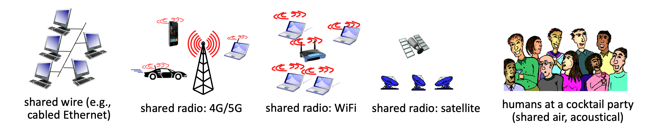
- Point-to-Point: A direct link between two nodes, such as a host and an Ethernet switch or a dial-up PPP connection.
- Broadcast (Shared Medium): A single channel shared by many nodes, like "old-school" bus Ethernet, WiFi, or 4G/5G cellular networks. If two nodes transmit simultaneously, a collision occurs, and the signals are scrambled.
- The Analogy: Think of a cocktail party where everyone shares the same air to speak; if two people talk at once, no one is understood.
MAC Protocol Taxonomy
Multiple Access Control (MAC) protocols are distributed algorithms that determine how nodes share the channel. Communication about channel sharing must use channel itself!
Ideally, given multiple access channel (MAC) of rate \(R\) bps
Desiderata:
- When one node wants to transmit, it can send at rate \(R\).
- When \(M\) nodes want to transmit, each can send at average rate \(R/M\)
- Fully decentralized:
- no special node to coordinate transmissions
- no synchronization of clocks, slots
- Simple
They generally fall into three categories:
-
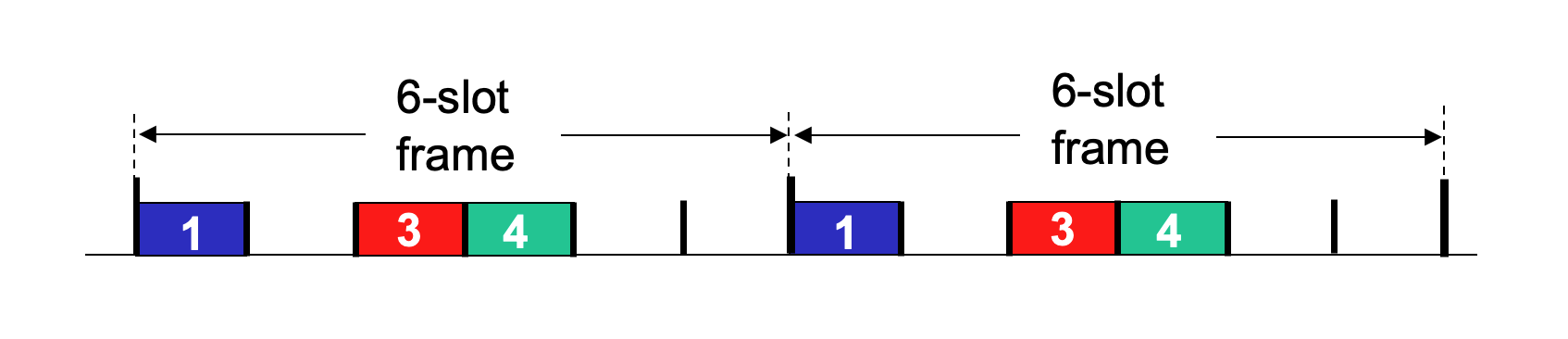
Channel Partitioning: Divides the channel into smaller, exclusive pieces (time slots or frequency bands).
-
TDMA (Time Division Multiple Access): Access is in "rounds." Each node gets a fixed length slot (length = packet transmission time) in every round. Unused slots go idle.
\(R/6\) rate for each slot for below example.
- FDMA (Frequency Division Multiple Access): Each node is assigned a fixed frequency band. Unused bands go idle.
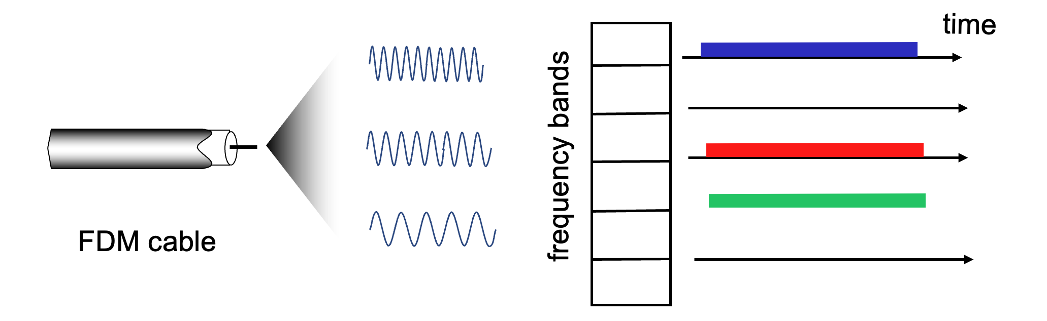
This shares channel efficiently and fairly at high load. However, it is inefficient at low load: delay in channel access, \(1/N\) bandwidth allocated even if only \(1\) active node!
-
-
Random Access: The channel is not divided. Nodes transmit at the full rate \(R\) whenever they have a packet. This allows collisions, but the protocol specifies how to detect and recover from them. Some examples include CSMA, CSMA/CD, CSMA/CA.
This is efficient at low load: single node can fully utilize channel. However, in high load: collision overhead.
-
"Taking Turns": Nodes take turns transmitting; those with more data can take longer turns.
Look for best of both worlds!
CSMA (Carrier Sense Multiple Access)
The core idea of CSMA is to "listen before you talk".
- Simple CSMA: A node senses the channel. If it's idle, the node transmits the entire frame. If it's busy, the node defers its transmission.
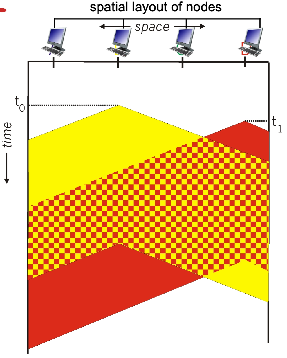
- The Collision Problem: Collisions can still occur due to propagation delay. Two nodes may start transmitting nearly simultaneously because they haven't yet "heard" the other's signal traveling across the wire.
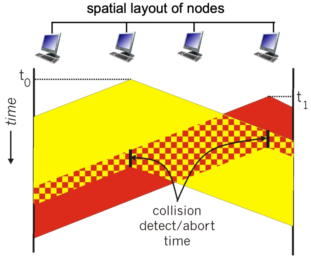
- CSMA/CD (Collision Detection): This is the "polite conversationalist" approach used in Ethernet.
- If a collision is detected, the node aborts immediately rather than finishing a useless transmission, significantly reducing channel wastage.
- Collision Detection:
- Easy in wired LANs: detect signal incoming signal energy while transmitting
- Difficult in wireless LANs: received signal strength overwhelmed by local transmission strength
- Collision Detection:
- Binary (Exponential) Backoff: After a collision, the node waits a random amount of time before retrying. As more collisions occur for the same frame, the range of the random wait time grows exponentially to reduce the chance of another collision.
- If a collision is detected, the node aborts immediately rather than finishing a useless transmission, significantly reducing channel wastage.
The Ethernet CSMA/CD Algorithm
The CSMA/CD (Carrier Sense Multiple Access with Collision Detection) algorithm is the specific "recipe" a Network Interface Card (NIC) follows to manage data transmissions on a shared physical wire. It is often compared to a "polite conversationalist" who listens before speaking and stops immediately if interrupted.
Step-by-Step Implementation
- Frame Creation: The NIC receives a datagram from the network layer and encapsulates it into an Ethernet frame.
- Carrier Sensing:
- The NIC "listens" to the channel.
- If the channel is idle: It starts the frame transmission immediately.
- If the channel is busy: It waits until it senses the channel is idle, then begins transmission.
- Transmission & Monitoring: While transmitting the frame, the NIC continues to monitor the wire to ensure no other node has started a transmission.
- Success: If the entire frame is sent without a collision being detected, the task is complete.
- Collision Detection: If the NIC detects another signal while it is still sending, a collision has occurred (likely due to propagation delay). It immediately aborts the transmission.
-
Jam Signal: After aborting, the NIC sends a "jam signal" to ensure all other nodes on the network recognize the collision and also stop transmitting.
- A jamming signal is a short, distinct bit pattern sent by a node immediately after it detects a collision.
- When two nodes transmit at the same time, their signals overlap and become garbled. Once a node realizes this has happened, it doesn't just stop talking; it broadcasts the jamming signal to ensure that every other node on the shared medium also recognizes the collision.
The node (or nodes) currently transmitting are the ones that send the jamming signal.
- Detection: While a node is transmitting bits, it is also "listening" to the wire. If it sees a voltage level higher than what it is sending, it knows a collision has occurred.
- The Jam: Instead of stopping immediately, the node continues to transmit for a few more moments, but it switches from sending its actual data to sending a 48-bit jamming signal.
- The Goal: It sends this "extra noise" to make sure the collision lasts long enough to travel down the entire cable. This ensures that every other node on the network—even a node at the very far end—definitely detects the collision and discards whatever garbled data it might have been receiving.
- The Stop: Only after sending the jamming signal does the node stop transmitting and start its random Exponential Backoff timer.
- Binary (Exponential) Backoff: The NIC enters a waiting period before trying again to avoid immediate re-collisions:
- After the \(m^{th}\) collision, the NIC chooses a random integer \(K\) from the set \(\{0, 1, 2, \dots, 2^m - 1\}\).
- The NIC waits for exactly \(K \cdot 512\) bit times (the time it takes to send \(512\) bits).
- The \(512\) bit times is not a random number; it is specifically tied to the Slot Time of a standard Ethernet network.
- Propagation Delay: It is the time required for a signal to travel to the end of the maximum allowed cable length and back.
- Minimum Frame Size: To ensure a node is still "on the line" when the collision signal returns, Ethernet has a minimum frame size of \(64\) bytes.
- The Math: \(64 \text{bytes}×8 \text{bits/byte}=512 \text{bits}\).
- The Result: It ensures that even in the worst-case distance, a node will not finish transmitting before it realizes a collision has occurred.
- The \(512\) bit times is not a random number; it is specifically tied to the Slot Time of a standard Ethernet network.
- After the wait, it returns to Step 2 to attempt the transmission again.
Explaining Binary Exponential Backoff
This mathematical approach prevents "death loops" where two nodes keep colliding forever.
- First Collision (\(m=1\)): \(K\) is chosen from \(\{0, 1\}\). There is a 50% chance the nodes pick the same number and collide again.
- Subsequent Collisions: As \(m\) increases, the range for \(K\) doubles (e.g., \(\{0, \dots, 3\}\), then \(\{0, \dots, 7\}\)).
- Result: The more "congested" the network is (more collisions), the further apart the nodes spread their retry attempts, allowing the traffic to "calm down" naturally.
CSMA/CD Minimum Frame Size Condition
See the pictures taken in class on March 23, 2026 for some blackboard explanations. Review them!!!
In CSMA/CD, a sender must still be transmitting when a collision from the farthest possible node propagates back.
Otherwise, the sender could finish sending the frame before noticing the collision.
Key condition
Let:
- \(L_{\min}\) = minimum frame size in bits
- \(R\) = link rate in bits/sec
- \(d_{\text{prop}}\) = one-way propagation delay
Then the sender's transmission time is:
For collision detection to work, this must be at least the round-trip propagation delay:
So:
If propagation delay is written as
where
- \(l\) = cable length
- \(v\) = propagation speed in the medium
then:
Why the factor of 2?
Because the worst-case collision scenario is:
- Station A starts transmitting
- The signal takes \(d_{\text{prop}}\) to reach the farthest station B
- B starts transmitting just before A's signal reaches it, causing a collision
- The collision takes another \(d_{\text{prop}}\) to propagate back to A
So A may need to wait up to:
before it can detect the collision.
Intuition
The rule is simply:
That is why the minimum frame size depends on:
- the network diameter / cable length
- the propagation speed
- the transmission rate
Deriving the Ethernet 512-bit minimum
Classic Ethernet chose a slot time of 51.2 microseconds.
- Slot time is the maximum round-trip propagation delay of the network.
For 10 Mbps Ethernet:
So the minimum frame size is:
Therefore:
Why 51.2 microseconds?
Ethernet was designed so that the maximum round-trip propagation delay of the network is at most one slot time:
Thus, if a sender transmits a frame of at least 512 bits, it is guaranteed to still be transmitting when a worst-case collision comes back.
Final result
For CSMA/CD:
and for classic 10 Mbps Ethernet:
This guarantees that collisions are detectable before transmission finishes.
Some Calculations
for \(i \geq 1\).
"Taking Turns" MAC Protocols
These protocols attempt to balance the efficiency of random access at low loads with the fairness of partitioning at high loads.
-
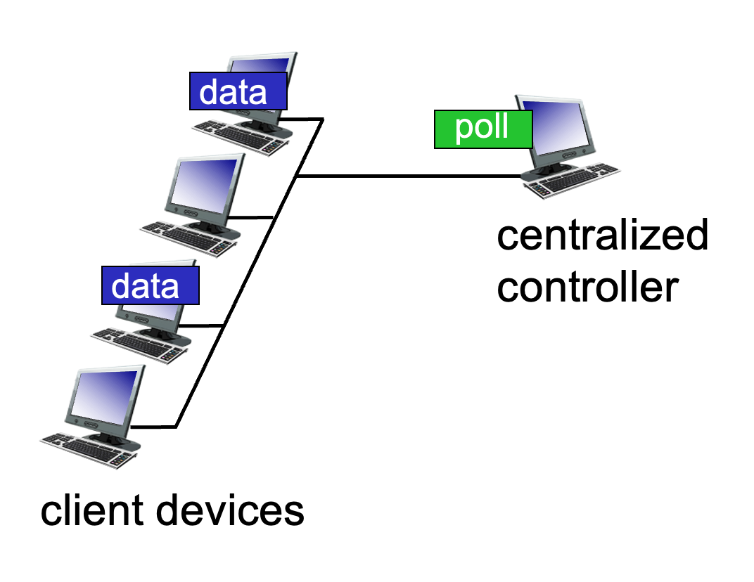
Polling: A centralized "master" node invites each "slave" node to transmit in turn.
- Pros: No collisions.
- Cons: Polling overhead, higher latency, and a single point of failure (if the master dies).
- Example: Bluetooth.

-
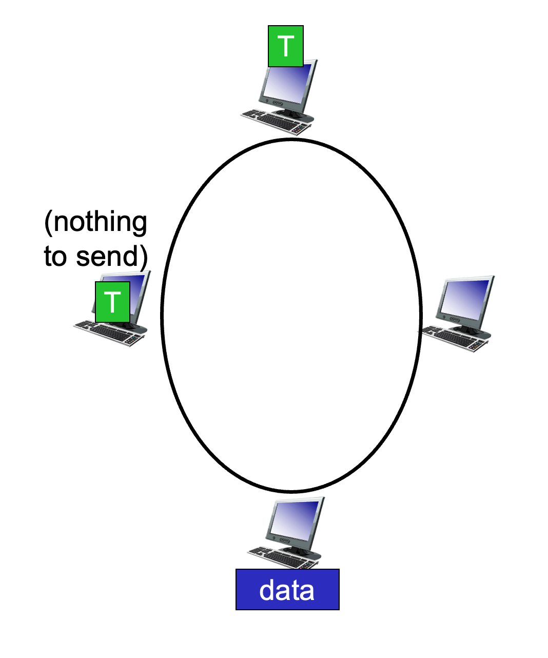
Token Passing: A special control "token" message is passed sequentially from one node to the next. A node can only transmit while holding the token.
- Concerns: Token overhead and the risk of the token getting lost.
Summary of MAC Protocol Taxonomy
| Class | Specific Protocols | Characteristics |
|---|---|---|
| Channel Partitioning | TDMA, FDMA | Fair/efficient at high load; inefficient at low load. |
| Random Access | ALOHA, CSMA, CSMA/CD, CSMA/CA | Efficient at low load; collision overhead at high load. |
| Taking Turns | Polling, Token Passing | Best of both worlds; used in Bluetooth and Token Ring. |
LANs
Comparison of IP and MAC Addressing
In networking, two types of addresses are essential for delivering data: IP addresses and MAC addresses. They function at different layers of the OSI model and serve distinct purposes.
- 32-bit IP Address:
- This is a network-layer address for an interface.
- It is used for Layer 3 (Network Layer) forwarding to move data across different networks.
- Analogy: It is like a postal address, which is hierarchical and depends on the specific location (subnet) where a node is attached.
- 48-bit MAC Address:
- Also known as a LAN, Physical, or Ethernet address.
- Function: Used "locally" to move a frame from one interface to another physically-connected interface within the same network.
- Structure: Usually expressed in hexadecimal notation (e.g.,
1A-2F-BB-76-09-AD), where each hex digit represents 4 bits. - Most are "burned-in" to the NIC (Network Interface Card) ROM, though some are software-settable.
- Analogy: It is like a Social Security Number, which is a "flat" address. This provides portability, meaning you can move a LAN card from one network to another and the MAC address remains the same.
MAC Address Allocation and LAN Structure
MAC addresses are managed globally to ensure that every network adapter (NIC) has a unique identity.
- Administration: The IEEE manages the allocation of MAC addresses.
- Manufacturing: Manufacturers purchase a portion of the MAC address space to ensure every card they produce is unique.
- LAN Visual: In a typical LAN (wired or wireless), every adapter has its own unique 48-bit identifier. Multiple computers connect to a shared LAN medium, and while they all have IP addresses for global routing, they use these unique MAC addresses to communicate with each other directly on the local segment.
ARP: Address Resolution Protocol
The Address Resolution Protocol (ARP) is the bridge between the Network Layer (IP) and the Data Link Layer (MAC).
The Core Problem
How does a device determine a specific interface's MAC address when it only knows that interface's IP address?
The ARP Table
Each IP node (host or router) on a LAN maintains an ARP Table.
- Contents: Mappings of
<IP address; MAC address; TTL>. - TTL (Time To Live): The time after which an address mapping will be forgotten (typically 20 minutes).
ARP Protocol Process within a Same LAN
When Host A wants to send a datagram to Host B, but B’s MAC address is not in A’s ARP table:
- Broadcast: Host A broadcasts an ARP query packet containing B's IP address. The destination MAC address for this broadcast is
FF-FF-FF-FF-FF-FF, ensuring all nodes on the LAN receive it. - Unicast Reply: Host B receives the packet and replies to A with its own MAC address. This reply is sent specifically to A’s MAC address (unicast).
-
Caching: Host A saves (caches) the IP-to-MAC mapping in its ARP table until it times out.
Situations where mapping changes
- Device disconnects/reconnects
- DHCP reassigns IP to a different device
- Network reconfiguration
- Virtual machines / containers
- Soft State: Information that times out unless refreshed is referred to as "soft state."
- Plug-and-Play: ARP is automatic; nodes create their tables without intervention from a network administrator.
Routing to Another LAN
When sending data to a destination outside the local network, the process involves both IP and MAC addressing across a router (R).
Walkthrough: Sending a Datagram from A to B via R
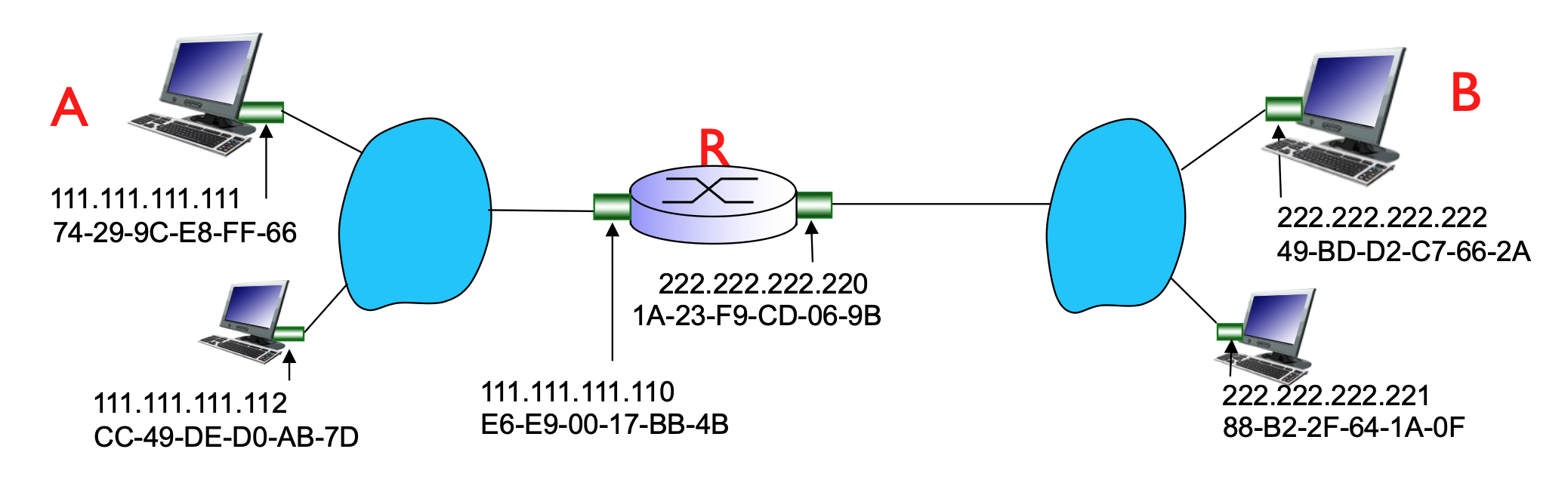
In this scenario, Host A (on network 111.111.111.xxx) wants to reach Host B (on network 222.222.222.xxx).
- Addressing Focus:
- At the IP layer, the focus is on the source (A) and the ultimate destination (B).
- At the MAC layer, the focus is on the "hop-by-hop" delivery.
-
The Process:
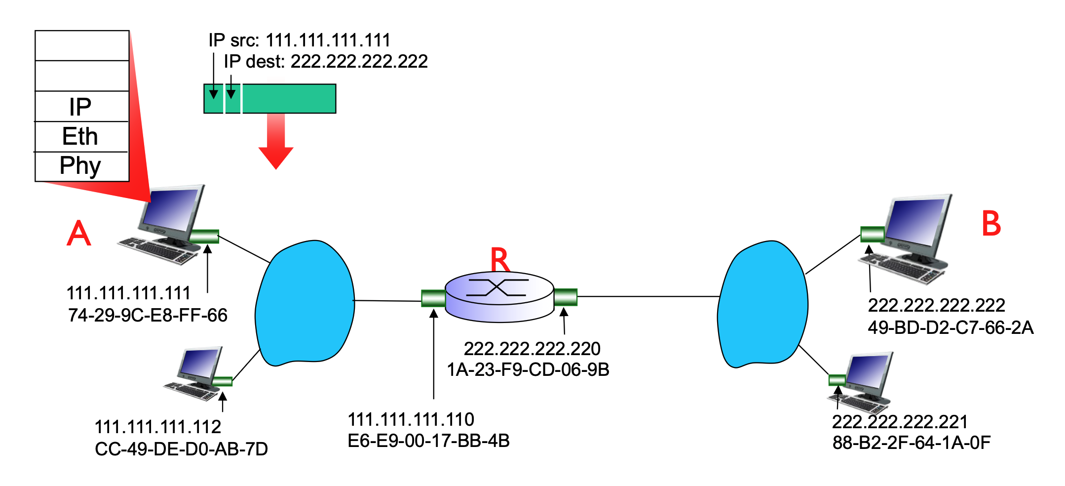
- Host A creates an IP datagram with source IP (A) and destination IP (B).
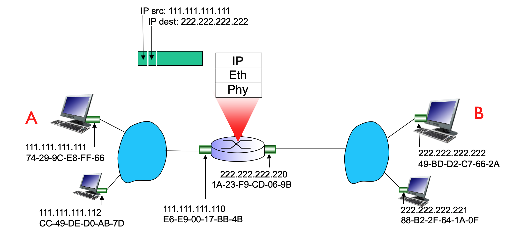
- Because B is on a different network, A must send the frame to its first-hop router (R).
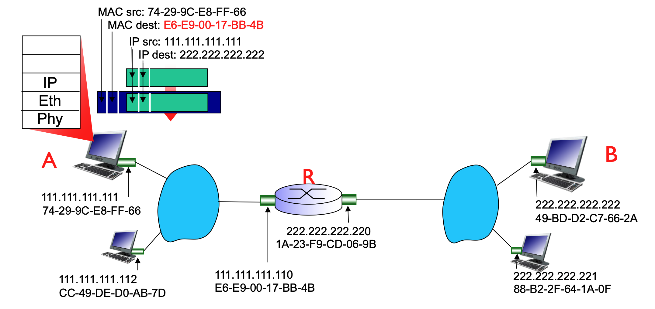
- A uses ARP to find the MAC address of the router's interface that is connected to A's LAN.
- A encapsulates the IP datagram into a link-layer frame. The destination MAC address of this frame is the router's interface MAC, even though the destination IP is Host B.
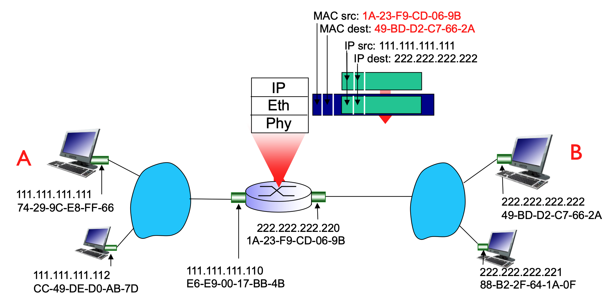
- The router receives the frame, strips the link-layer header, looks at the destination IP (B), and sees it must forward it to the 222.222.222.xxx network.
- The router then uses ARP to find Host B’s MAC address and encapsulates the datagram into a new frame to be delivered to B.
- ARP is sent only on the subnet of the outgoing interface, to resolve the MAC of the next-hop IP.
-
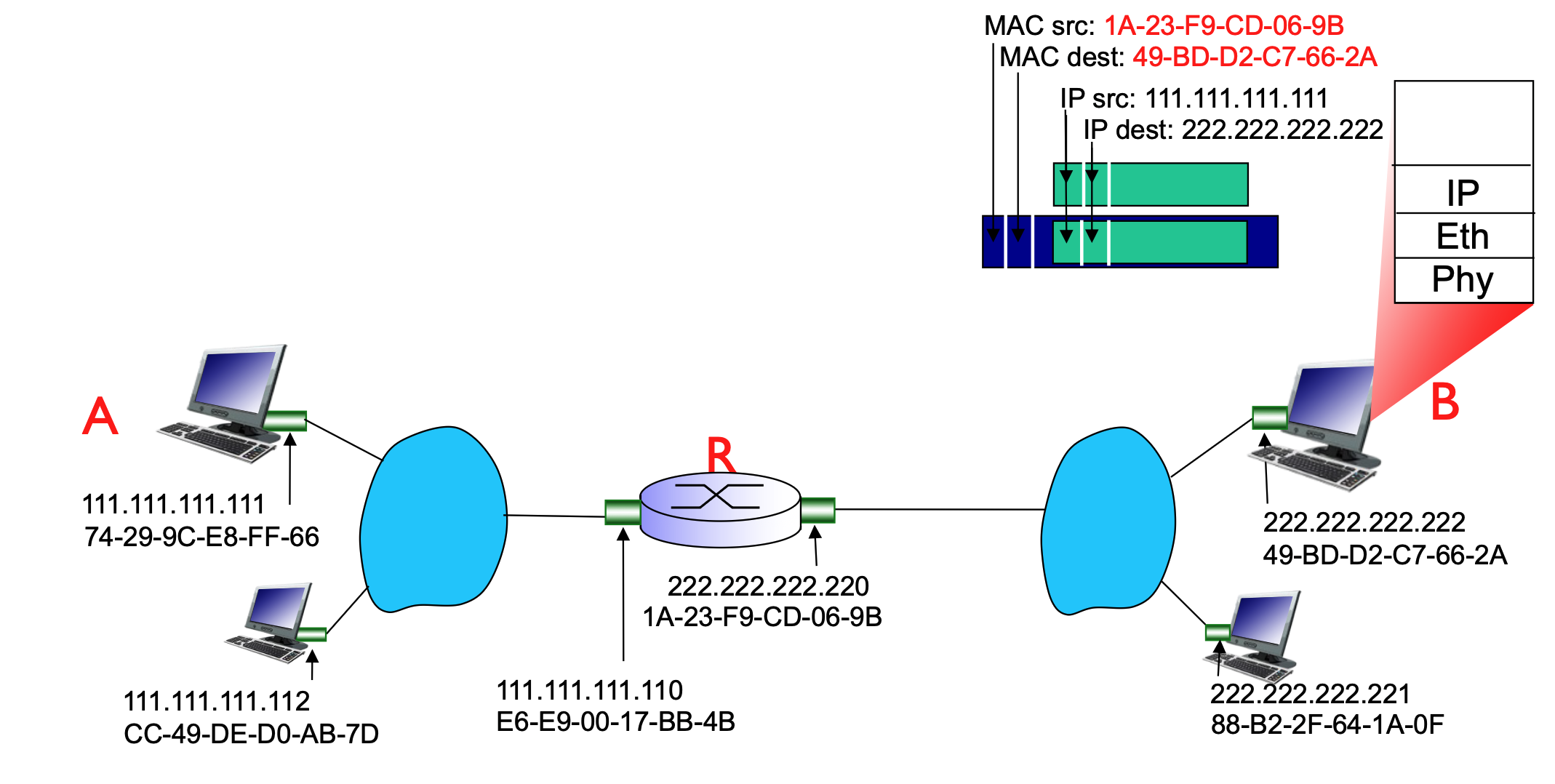
Finally, B receives the datagram from A
Inside the same subnet, the MAC address does NOT change. MAC only changes when crossing routers (between subnets).
The router connects multiple subnets, and each interface belongs to one subnet.
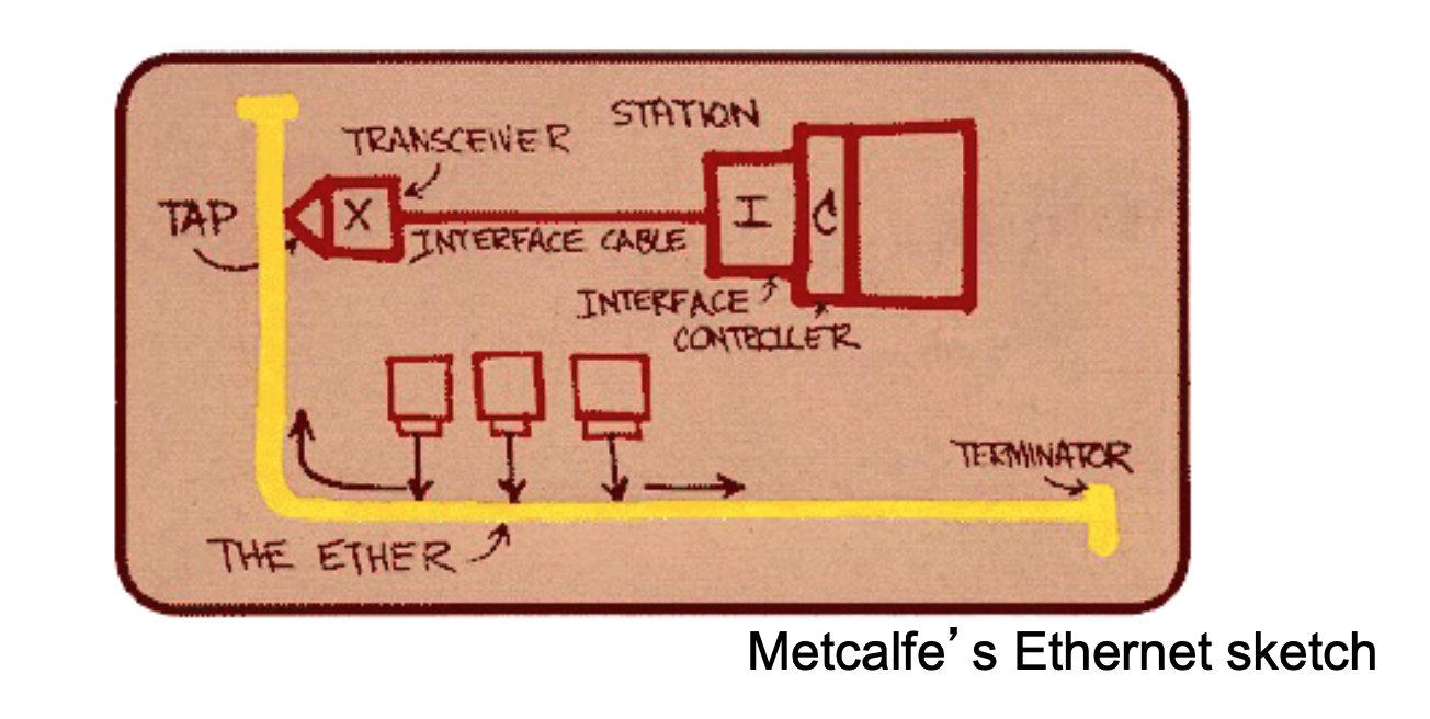
Ethernet Overview
Ethernet is the "dominant" wired LAN technology because it is inexpensive, simple, and has evolved significantly in speed.

- Key Characteristics:
- Cost-effective: Network Interface Cards (NICs) are very cheap (approx. $20).
- Evolution: It was the first widely used LAN technology and has kept pace with speed demands, growing from 10 Mbps to 10 Gbps.
- Comparison: It is simpler and cheaper than alternative technologies like Token Ring LANs and ATM (Asynchronous Transfer Mode).
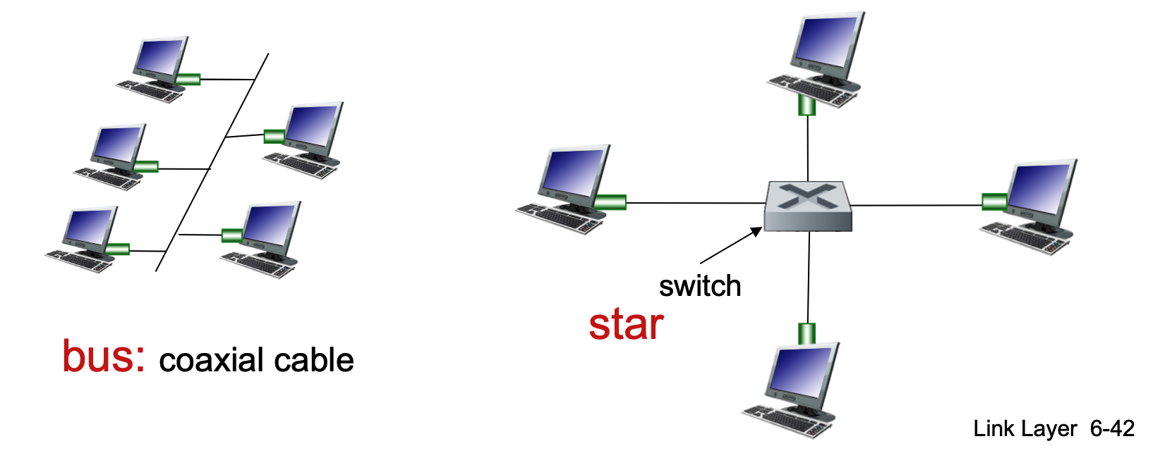
Physical Topology
The way nodes are physically connected has changed over time:

- Bus Topology (Popular through mid-90s):
- All nodes are connected to a single coaxial cable.
- Nodes are in the same collision domain, meaning they can collide with each other if they transmit at the same time.
- Star Topology (Prevails today):
- Features an active switch in the center.
- Each node has a dedicated "spoke" connection to the switch.
- Nodes do not collide with each other because the switch manages the traffic.
- If the collision happens, it will happen only on one side/connection, which means that it will not affect others.
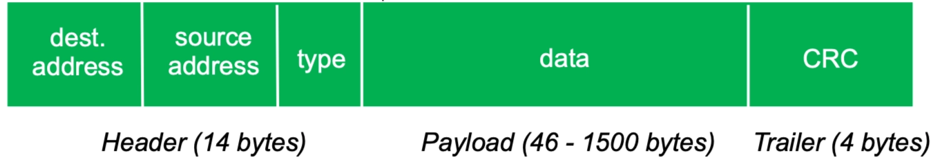
Ethernet Frame Structure
The sending adapter encapsulates an IP datagram (or other network-layer packet) into an Ethernet frame.
- Frame Fields:
- Dest. & Source Address: 6-byte (48-bit) MAC addresses.
- Type: Indicates the higher-layer protocol. Common values include 0x0800 (IPv4), 0x0806 (ARP), and 0x86DD (IPv6).
- Data (Payload): Typically 46 to 1500 bytes.
- CRC (Cyclic Redundancy Check): A 4-byte trailer used at the receiver to detect bit-level errors. If an error is detected, the frame is dropped.
- Note that the minimum size of the frame is 64 bytes, which is 512 bits! Seem familiar!?
- Address Filtering: If an adapter receives a frame with a matching destination MAC address (or a broadcast address), it passes the data to the network-layer protocol. Otherwise, it discards the frame.
Unreliable and Connectionless Service
Ethernet provides a simple, "best-effort" delivery service at the link layer.
- Connectionless: There is no handshaking between the sending and receiving NICs before sending frames.
- Unreliable: The receiving NIC does not send acknowledgments (ACKs) or negative acknowledgments (NAKs).
- Dropped data is only recovered if the initial sender uses a higher-layer protocol that provides reliable data transfer (e.g., TCP).
- Otherwise, the data is lost.
- MAC Protocol: Uses CSMA/CD with binary backoff specifically in half-duplex configurations.
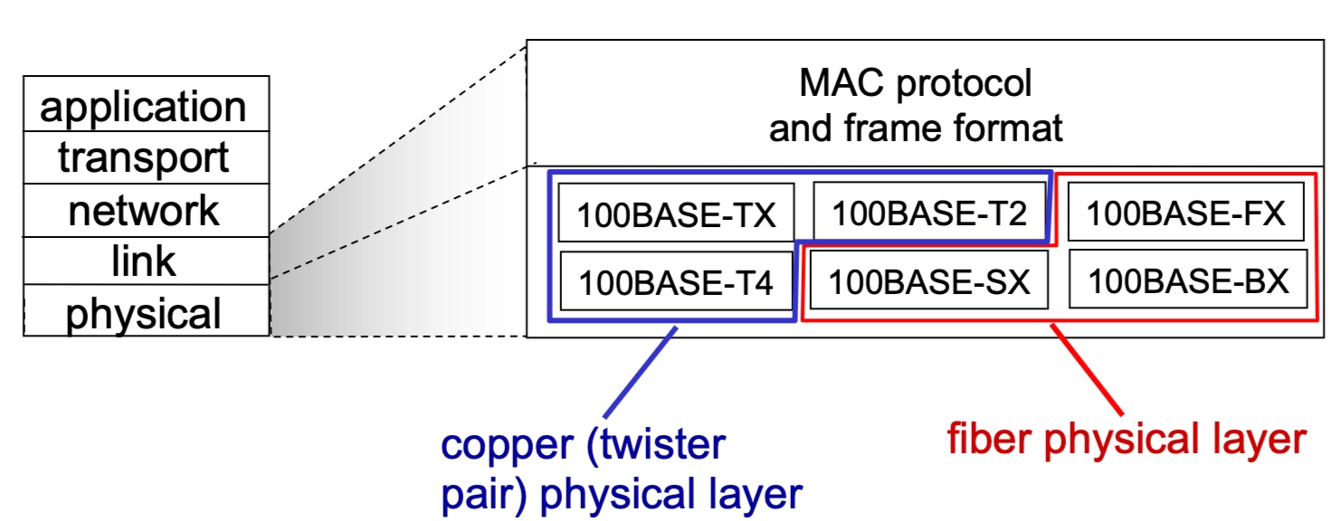
Ethernet Standards (802.3)
The IEEE 802.3 standards encompass many different versions that share a common MAC protocol and frame format but differ in speed and physical media.
- Speeds: Range from 2 Mbps to 10 Gbps.
- Physical Media: Includes fiber optic and copper (twisted pair).
- Examples: 100BASE-TX (Copper), 100BASE-FX (Fiber).
Ethernet Switches
A switch is a link-layer device that takes an active role in the network.
- Core Functions:
- Stores and forwards Ethernet frames.
- Examines incoming MAC addresses and selectively forwards frames to the necessary outgoing links.
- Uses CSMA/CD to access segments in half-duplex (though modern switches often run in full-duplex where CSMA/CD is not needed).
- Half-duplex → one shared channel, many devices, collisions possible
- Any network using a hub is automatically half-duplex. A hub (Layer 1 devide) doesn’t control traffic - it just blindly repeats signals to all ports, leaving devices to deal with collisions.
- Because the hub sends every signal to every device, if two devices try to "talk" at the same moment, the electrical signals overlap on the wire. This results in a collision, rendering the data unreadable.
- Any network using a hub is automatically half-duplex. A hub (Layer 1 devide) doesn’t control traffic - it just blindly repeats signals to all ports, leaving devices to deal with collisions.
- Full-duplex → one dedicated link per pair of devices, no collisions
- CSMA/CD is not needed in full-duplex Ethernet because there is no shared medium and therefore no possibility of collisions: each device has a dedicated point-to-point link to the switch, with separate channels for sending and receiving, allowing both sides to transmit simultaneously without interfering with each other. In contrast, CSMA/CD is only required in half-duplex networks where multiple devices share the same segment and must coordinate access to avoid collisions.
- Full-duplux is not one link for sending and another separate link for receiving but one connection, internally split into two independent directions.
- Half-duplex → one shared channel, many devices, collisions possible
- Transparency: Hosts are unaware of the switch's presence.
- Plug-and-play / Self-learning: Switches do not need manual configuration.
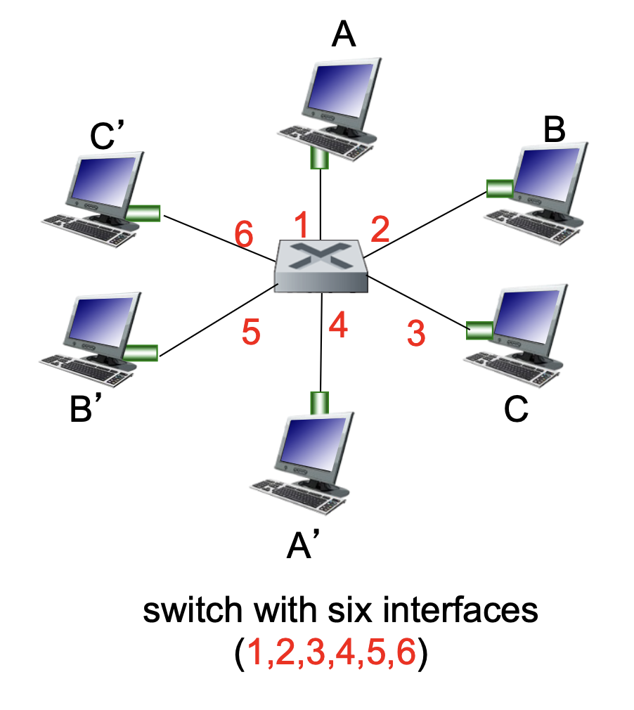
Switch Operation and Self-Learning
Switches allow for multiple simultaneous transmissions without collisions.
- Dedicated Connections: Each host has a direct connection to a switch interface.
- Buffering: The switch buffers incoming packets to manage flow.
- Switching: If Host A sends to A' and Host B sends to B', the switch can process both transmissions simultaneously.
- Switch Table: Each switch maintains a table with entries consisting of:
(MAC address of host, Interface to reach host, Time stamp).- It looks like a routing table!
- The Learning Process:
- When a frame is received, the switch "learns" the location of the sender by recording the incoming interface and the sender's MAC address.
- This pair is recorded in the switch table with a TTL (Time to Live).
Switch: Frame Filtering and Forwarding
When a switch receives a frame, it follows a specific logical process to decide whether to drop the frame, forward it to a specific link, or broadcast it to everyone.
The Forwarding Algorithm
- Record: The switch records the incoming link and the MAC address of the sending host to update its internal table.
- Index: The switch looks up the MAC destination address in its switch table.
- Decision:
- If entry is found:
-
If the destination is on the same segment from which the frame arrived \(\rightarrow\) Drop the frame (it has already reached its destination segment).
- Frame comes into the switch on port X; The switch knows the destination is also reachable via port X; Both sender and receiver are on the same segment (same port); The frame is already delivered on that link; If the destination is in that same “group,” the switch doesn’t need to forward it anywhere else.
- When a switch receives a frame, it checks which port the destination device is on using its MAC table; if the destination is on the same port (same segment) that the frame arrived on, the switch drops the frame because it has already been delivered directly over that shared segment (e.g., via a hub or shared medium). In other words, both hosts can already “see” each other’s transmissions without the switch needing to forward anything, so forwarding would be redundant and unnecessary.
- Example
A → Hub → (B, C, Switch S₁ on port S₁P1) # P1 is a port on the switch # A, B, C are all connected to the same hub # The hub connects to S₁ via port S₁P1 -> So they are all on the same segment (same switch port)- A sends a frame
- Hub receives the electrical signal
- Hub: sends the same signal to every other port
- So B, C and Switch receives it.
- The hub is not “deciding” to broadcast, it’s just blindly repeating signals.
- Otherwise \(\rightarrow\) Forward the frame on the specific interface indicated by the table entry.
- If entry is NOT found:
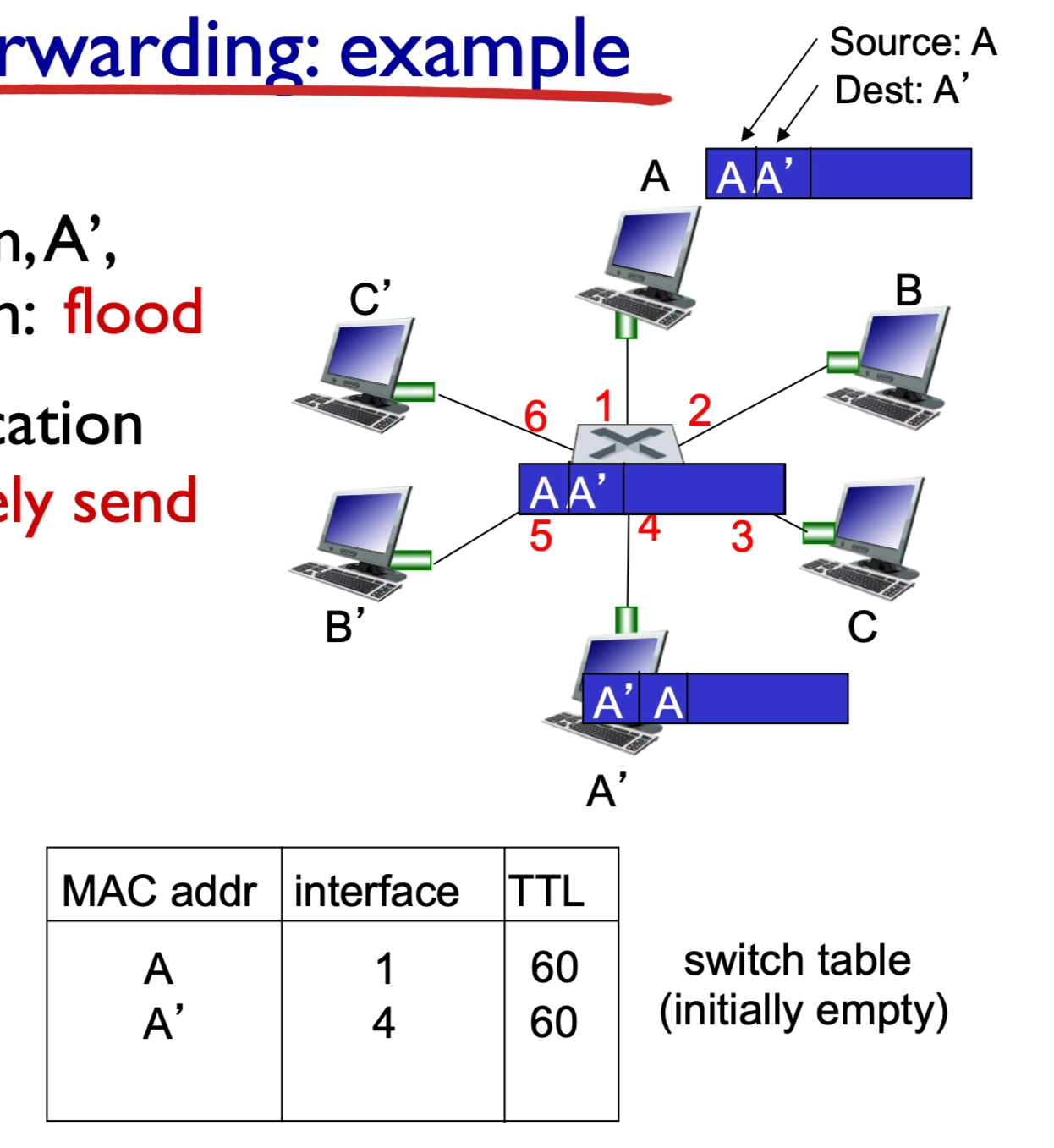
- Flood: Forward the frame on all interfaces except the one it arrived on.
- If entry is NOT found:
- Forwards (floods) the original frame unchanged.
- Sends it to all ports except the incoming one.
1. The ARP Request (Broadcast Flooding)
Host uses ARP to map IP → MAC
- The "Reason": Host A has an IP address (e.g.,
192.168.1.5) but doesn't know which MAC address owns it. - The Frame: The destination MAC is set to
FF:FF:FF:FF:FF:FF. - Switch Logic: When a switch sees an "All-Fs" broadcast address, its rule is: "This is for everyone. Send it out every port except the one it came in on."
- Outcome: Every device receives it, but only the owner of that IP replies.
2. The Switch's "Learning" (Unknown Unicast Flooding)
This happens purely at Layer 2.
The frame has a specific destination MAC address. So by definition, it is a unicast frame (meant for one device).
- The "Reason": Host A knows the destination MAC (it already did the ARP or it's in its cache), but the switch has forgotten which port that MAC is plugged into (or the MAC table entry timed out).
- The Frame: The destination is a specific MAC (e.g.,
00:AA:11:BB:22:CC). - Switch Logic: The switch looks at its MAC Address Table and sees no match. Its rule is: "I don't know where this specific guy is. To be safe, I'll flood it to everyone and see who grabs it."
- Outcome: When the destination device receives it and replies, the switch "learns" the port and updates its table.
-
- If entry is found:
In the switching logic shown, it assumes the frame already has a destination MAC address (because switches operate at Layer 2). If the sender (Host A) doesn’t know the destination MAC, it must first use ARP: A sends an ARP request (a broadcast frame) asking “Who has this IP?”. That ARP request is then flooded by the switch to all ports (since broadcasts are always flooded). The correct host replies with its MAC address, and after that A can send the actual data frame using that MAC. So ARP is used when the MAC is unknown, and ARP requests are also flooded, but for a different reason (they are broadcasts, not unknown unicasts).
Self-Learning and Forwarding Example
The switch builds its table dynamically as it processes traffic.
- Scenario 1: Destination Unknown (Flooding): If Host A sends a frame to A' and the switch does not know where A' is, it floods the frame to all ports.
- When a switch receives a frame from Host A destined for A′ but does not yet know which port A′ is on, it performs flooding by sending the frame out all ports except the one it arrived on. All hosts receive the frame, but only the correct destination (A′) processes it and responds if the protocol requires a reply (e.g., ARP or ping), and this response typically includes the relevant result or data (such as a MAC address, acknowledgment, or requested content). When A′ sends this response, the switch observes the source MAC address and the incoming port, allowing it to learn A′’s location and update its forwarding table for future frames.
- It sends the frame out all ports except the incoming one. So every device connected to those ports will receive the frame.
- Scenario 2: Destination Known (Selective Forwarding): Once A' replies or sends its own traffic, the switch "learns" its location. The next time a frame is sent to A', the switch selectively sends it on just the one correct link.
- Table Updates: Each entry includes a MAC address, the corresponding interface, and a TTL (Time to Live) to ensure the information stays current.
- Switches are passive learners
- They don’t ask “where are you?”
- They only learn when a device talks
Interconnecting Switches
Switches can be connected to other switches to create larger, more complex network hierarchies.
- Hierarchical Structure: Multiple switches (e.g., \(S_1, S_2, S_3\)) can connect to a central backbone switch (\(S_4\)).
- Scalability: Self-learning works exactly the same in a multi-switch environment as it does in a single-switch case.
- Example: If Host A sends a frame to Host G, switch \(S_1\) learns that G is reachable via the link to \(S_4\). \(S_4\) then learns G is reachable via \(S_3\), and so on.
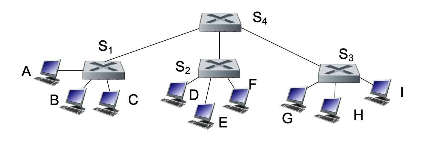
Note
- S₁A = port on S₁ connected to A
- S₁S₄ = port on S₁ connected to S₄
1. A sends frame
- Frame: (src=A, dst=G)
- Enters S₁ via S₁A
- Frame is NOT changed
2. S₁ processes
- Learns: A → S₁A
- G unknown → flood
- Sends copies out: S₁B, S₁C, S₁S₄
- Frame content unchanged (same src/dst MAC)
3. Hosts B and C receive
- They check destination MAC: Not equal to their MAC
- Ignore the frame
- They do NOT reply
- Switch learns nothing from them
4. S₄ receives (via S₄S₁)
- Learns: A → S₄S₁
- G unknown → flood
- Sends copies to: S₄S₂, S₄S₃
- Frame unchanged
5. S₂ receives (via S₂S₄)
- Learns: A → S₂S₄
- Floods to: S₂D, S₂E, S₂F
- D, E, F: Receive → not destination → ignore
- Frame unchanged
6. S₃ receives (via S₃S₄)
- Learns: A → S₃S₄
- Floods to: S₃G, S₃H, S₃I
7. Hosts H and I receive
- Not destination → ignore
- No reply
8. G receives (via S₃G)
- Destination matches
- Processes frame
- Sends reply
Reply: G → A
9. G sends reply
- New frame: (src=G, dst=A)
- This is a NEW frame, not modified original
10. S₃ processes
- Learns: G → S₃G
- Knows A → S₃S₄
- Forwards (no flooding)
11. S₄ processes
- Learns: G → S₄S₃
- Forwards to S₄S₁
12. S₁ processes
- Learns: G → S₁S₄
- Forwards to S₁A
Important clarifications
Do switches modify the frame?
No (in normal Layer 2 switching)
- Source MAC = A
- Destination MAC = G
- Stays the same across switches
How do non-destination hosts behave?
- They receive the frame physically
- They check destination MAC
- If not matching:
- drop silently
- no response
- no learning by switch
Final intuition
- Flooding = “try everywhere”
- Only G responds
- Switches learn only from senders
- Reply builds the correct path
Flooding itself does NOT require a response
-
Flooding just means:
“Send this frame everywhere because I don’t know where it goes”
- Whether someone replies depends on the protocol inside the frame
Switches vs. Routers
While both devices are used to connect segments of a network, they operate at different layers and use different logic.
| Feature | Switches | Routers |
|---|---|---|
| Layer | Link-layer (Layer 2) | Network-layer (Layer 3) |
| Headers | Examine Link-layer headers | Examine Network-layer headers |
| Forwarding Basis | MAC Addresses | IP Addresses |
| Table Creation | Learning, flooding, and MAC addresses | Routing algorithms and IP addresses |
| Protocol | Plug-and-play; self-learning | Requires configuration and routing protocols |
A switch (Layer 2) forwards frames without changing their source or destination MAC addresses—meaning the original source MAC (sender) and destination MAC (receiver) remain the same end-to-end across switches. In contrast, a router (Layer 3) removes the incoming Ethernet frame, examines the destination IP address, and then creates a new frame for the next hop with a new source MAC (the router’s outgoing interface) and new destination MAC (the next-hop device); thus, MAC addresses change at every router hop, while IP addresses remain the same end-to-end (aside from updates like TTL).
Common Ground
Both switches and routers use store-and-forward logic, meaning they receive the entire packet/frame and check for errors before sending it to the next destination, and both have forwarding tables.
Motivation for VLANs
A standard Local Area Network (LAN) operates as a single broadcast domain. As these networks grow, several challenges arise:
- Scaling Issues: All Layer-2 broadcast traffic (such as ARP queries, DHCP requests, or frames with unknown destination MAC addresses) must cross the entire LAN. This consumes significant bandwidth as the number of nodes increases.
- Efficiency & Performance: Large broadcast domains lead to high levels of unnecessary traffic for most nodes.
- Security and Privacy: Within a single broadcast domain, sensitive data can be more easily intercepted by unauthorized users on the same physical segment.
- Administrative/Organizational Flexibility: In a traditional setup, a user's network identity is tied to their physical location.
- Example: If a Computer Science (CS) student moves their office to the Electrical Engineering (EE) building, they are physically attached to the EE switch but may want to remain logically attached to the CS network.
Port-based VLANs
VLAN technology allows switch(es) to be configured to define multiple virtual LANs over a single physical LAN infrastructure.
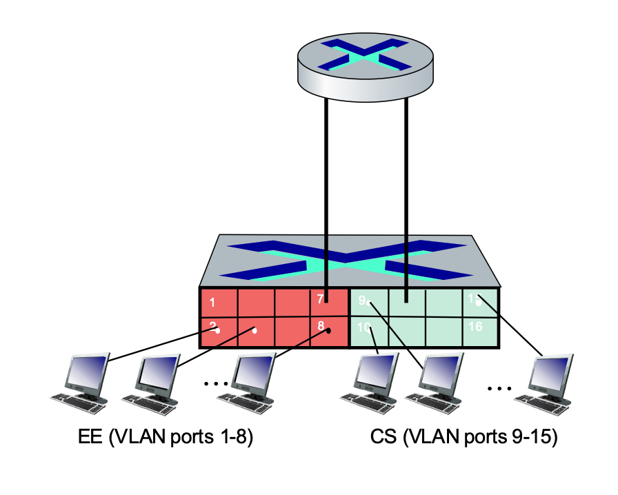
- Definition: In a port-based VLAN, switch ports are grouped by management software.
- Virtual Segmentation: A single physical switch can be partitioned so it operates as if it were multiple independent virtual switches.
- Example: Ports 1-8 can be assigned to the EE department, while ports 9-15 are assigned to the CS department.
Key Features of Port-based VLANs
- Traffic Isolation: Frames sent to or from ports 1-8 can only reach other ports within that same group (1-8).
- Alternative Grouping: While port-based is common, VLANs can also be defined based on the MAC addresses of endpoints.
- Dynamic Membership: Ports can be dynamically reassigned among different VLANs through software without changing physical wiring.
- Forwarding Between VLANs: Communication between different VLANs is done via routing, just as it would be between separate physical switches. Modern vendors often sell "Layer 3 switches" which combine switching and routing capabilities in one device.
- VLANs behave like completely separate physical networks.
- If it is a layer 2 switch, even on the same physical switch, traffic between VLANs must go through a router.
VLANs Spanning Multiple Switches
In many organizations, a single VLAN (like "Accounting" or "Engineering") needs to exist across multiple physical switches in different buildings or floors.
- Trunk Port: A specialized port that carries frames between VLANs defined over multiple physical switches.
- The Need for Tagging: Frames forwarded within a VLAN between switches cannot be "vanilla" 802.1 Ethernet frames because the receiving switch needs to know which VLAN the frame belongs to.
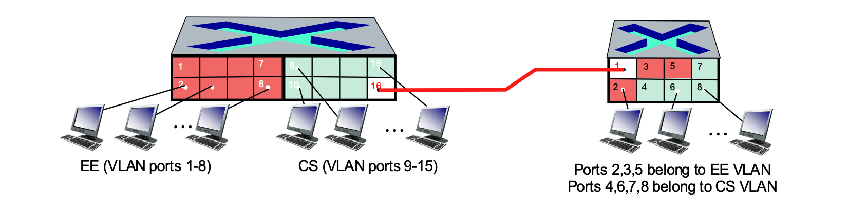
Access Ports
The ports connecting to the individual computers are access ports.
- Function: These ports are members of a single, specific VLAN (e.g., ports 1-8 on the left switch for EE, or ports 9-15 for CS).
- Behavior: They carry "untagged" traffic. When a computer sends a standard Ethernet frame to an access port, the switch understands which VLAN it belongs to based on the port's configuration.
- Identification in Image: On the left switch, ports 1-8 (Red) and 9-15 (Green) are access ports. On the right switch, ports 2-8 are access ports assigned to either the EE or CS VLANs.
Trunk Ports
The port connected to the red line bridging the two switches is a trunk port.
- Function: A trunk port is designed to carry traffic for multiple VLANs simultaneously over a single physical link.
- Behavior: Unlike access ports, trunk ports use 802.1Q tagging. The switch adds a "tag" to each frame to identify which VLAN it belongs to (EE or CS) so the receiving switch knows how to handle it.
- Identification in Image: Port 16 on the left switch and Port 1 on the right switch serve as the trunk ports for this network.
The "type" of frame depends entirely on where the frame is currently traveling, not just which VLAN it belongs to.
Within the Same Physical Switch
If a host on the EE VLAN sends a frame to another host on the EE VLAN connected to the same switch:
- Standard Ethernet Frame: The frame remains a standard, "untagged" Ethernet frame.
- Direct Forwarding: The switch receives the frame on one access port and forwards it directly to the destination access port. No VLAN header is added because the switch already knows both ports belong to the same EE "broadcast domain."
Across Multiple Switches (The Trunk Port)
If a host on the EE VLAN on the left switch needs to reach a host on the EE VLAN on the right switch:
- The Role of the Trunk: The frame must travel across the link connecting the two switches.
- Adding the Header (Tagging): As the frame exits the left switch through the trunk port, the switch modifies the frame by inserting the 802.1Q VLAN header (the tag). This tag identifies the frame as belonging to the "EE VLAN."
- Removing the Header (Detagging): When the right switch receives the frame on its trunk port, it reads the tag, realizes it belongs to the EE VLAN, and then strips the tag off.
- Delivery: The right switch then delivers a standard, untagged Ethernet frame to the destination host's access port.
Summary of Frame State
- At the Access Port: Always a standard Ethernet frame (no VLAN header). The end-device (PC) has no idea VLANs even exist.
- On the Trunk Link: Always a tagged 802.1Q frame (contains the VLAN ID). This allows one cable to carry traffic for many different VLANs without them getting mixed up.
Key Distinction: Different VLANs
Note that if you are trying to send data from the EE VLAN to the CS VLAN, the switch will not simply send it across a trunk or access port. Because they are separate networks, the traffic must be sent to a Router (or a Layer 3 Switch) to be routed between the two virtual networks, even if the hosts are plugged into the same physical box.
802.1Q VLAN Frame Format
The IEEE 802.1Q protocol defines a standard for "tagging" frames so they can carry VLAN information across trunk links.
Comparison of Frame Formats
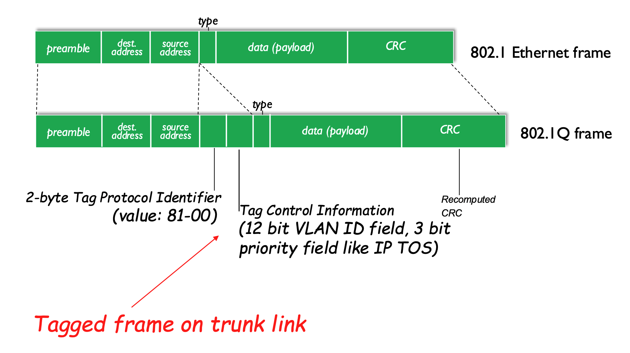
- Standard 802.1 Ethernet Frame: Contains Preamble, Dest/Source Address, Type, Data, and CRC.
- Used by access ports.
- 802.1Q Tagged Frame: Inserts a 4-byte "tag" into the header:
- Used by trunk ports.
- 2-byte Tag Protocol Identifier: A fixed value (0x8100) that identifies the frame as an 802.1Q tagged frame.
- Tag Control Information:
- VLAN ID (12 bits): The specific ID of the VLAN.
- Priority Field (3 bits): Used for Quality of Service (QoS), similar to IP Type of Service (TOS).
- Recomputed CRC: Because the header has been modified, a new Cyclic Redundancy Check (CRC) value is calculated for the trailer.
- Every time we add or remove a header, we have to recompute the CRC.
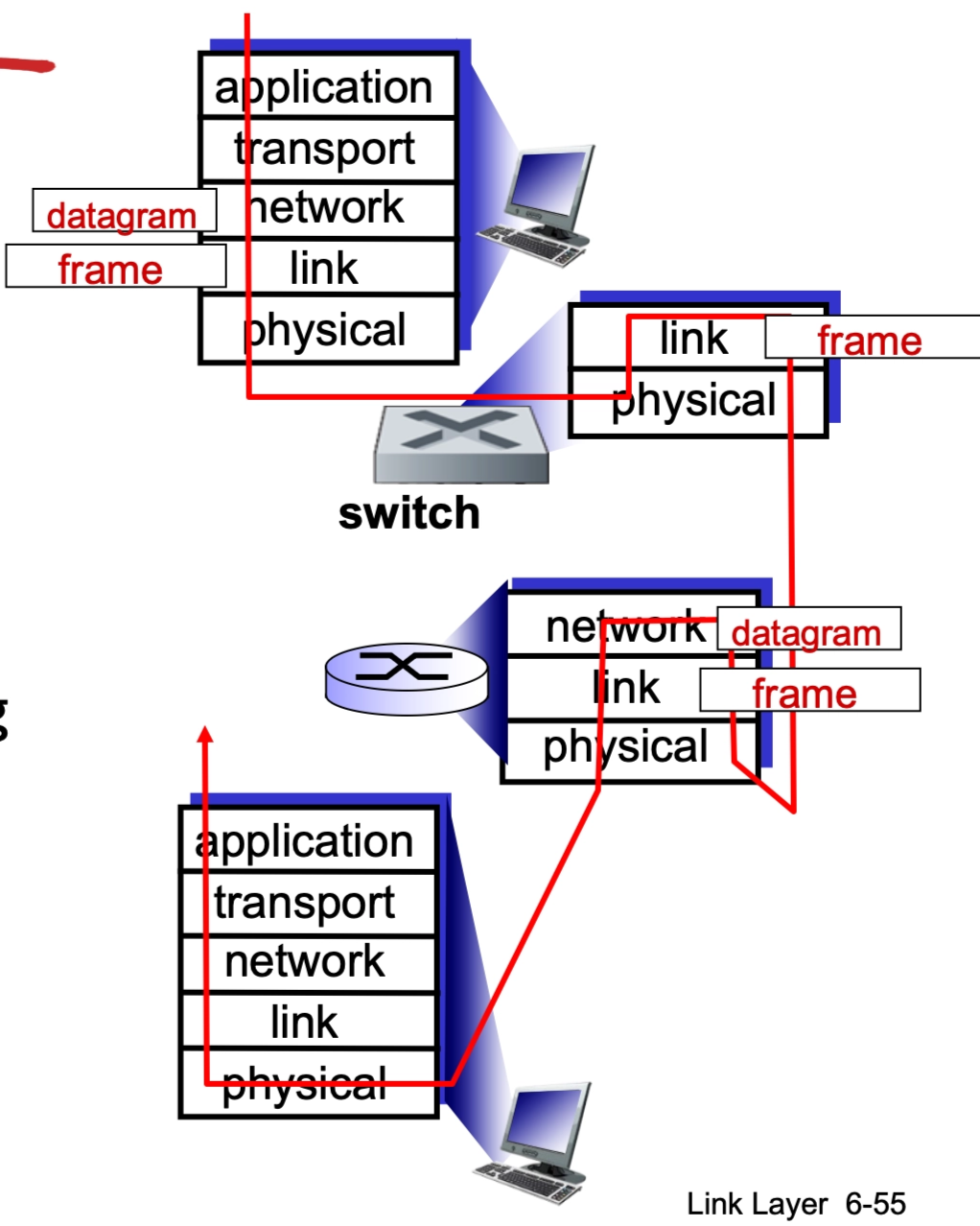
A Day in the Life of a Web Request
This section reviews the entire protocol stack (Application, Transport, Network, Link) by synthesizing a seemingly simple scenario: a student connects a laptop to a campus network and requests www.google.com.
Connecting to the Internet (DHCP)
Before any web browsing can happen, the laptop must obtain its own network configuration.
- Goal: The laptop needs its own IP address, the address of the first-hop router, and the address of the DNS server.
- Protocol: DHCP (Dynamic Host Configuration Protocol).
- The Process:
- The DHCP request is encapsulated in UDP, then in IP, and finally in 802.3 Ethernet.
- The Ethernet frame is broadcast (destination MAC:
FF-FF-FF-FF-FF-FF) on the LAN. - A router running a DHCP server receives and demultiplexes the frame up to the DHCP layer.
- The server formulates a DHCP ACK containing the client's allocated IP, the first-hop router's IP, and the DNS server's name/IP.
- The frame is forwarded back to the client (using switch learning), and the client now has the configuration needed to communicate.
Address Resolution (ARP)
Before the laptop can send a DNS query or an HTTP request, it must be able to send frames to its first-hop router.
- The Problem: The client knows the router's IP but not its MAC address.
- Protocol: ARP (Address Resolution Protocol).
- The Process:
- The client broadcasts an ARP query.
- The router receives the query and replies with an ARP reply containing its MAC address.
- The client now has the MAC address necessary to send link-layer frames to the router.
Resolving the Domain Name (DNS)
To contact Google, the laptop needs the actual IP address associated with the URL.
- Protocol: DNS (Domain Name System).
- The Process:
- A DNS query is created, encapsulated in UDP/IP/Ethernet, and sent to the first-hop router.
- The IP datagram is routed through the network (using tables created by protocols like RIP, OSPF, IS-IS, and BGP) until it reaches the DNS server.
- The DNS server replies with the IP address for
www.google.com.
The Web Request (TCP and HTTP)
With the destination IP address known, the laptop can finally initiate the web request.
1. Establishing a Connection (TCP)
- The client must open a TCP socket to the web server.
- 3-way Handshake:
- Client sends a TCP SYN segment.
- Web server responds with a TCP SYNACK.
- The TCP connection is established.
2. Request and Reply (HTTP)
- HTTP Request: The client sends the actual HTTP request into the TCP socket.
- Routing: The IP datagram containing the request is routed across the internet to Google's web server.
- HTTP Reply: Google's web server responds with an HTTP reply containing the web page data.
- Completion: The IP datagram containing the reply is routed back to the client, and the web page is finally displayed in the browser.
Summary of the Journey
The journey down the protocol stack is now complete. This synthesis demonstrates how multiple independent protocols and principles (DHCP, ARP, DNS, TCP, and HTTP) work in practice to facilitate a single user action.
Questions
- Does a router belong to different subnets? So when it wants to know the MAC address, it will send a ARP query to that subnet?
- Yes—a router belongs to multiple subnets, with each of its interfaces assigned an IP address in a different subnet, allowing it to connect those networks together. When the router needs to forward a packet, it first uses its routing table to determine the correct outgoing interface and next hop (either a final host or another router). To actually send the frame on that link, it must know the MAC address of the next hop, so it uses ARP—but importantly, it sends the ARP request only within the specific subnet associated with the outgoing interface, not across all subnets. The device with the matching IP (next hop) replies with its MAC address, enabling the router to encapsulate the packet in a frame with the correct destination MAC and forward it.
- When the A’ receives the request, will it send back its MAC address or with a response?
- It depends on the type of request (the protocol). If the request is an ARP request, then A′ sends an ARP reply that explicitly includes its MAC address (along with its IP), since that is the result being requested. If it is a normal data request (e.g., ping or an application request), A′ sends a protocol-specific response that includes the requested result or data (such as an ICMP reply or application content), and its MAC address is included automatically in the source MAC field of the reply frame, not as a separate piece of data.
- Flooding does not require a reply by itself—it’s just what the switch does when it doesn’t know where to send a frame (it sends it out all ports). Whether a reply happens depends entirely on the protocol inside the frame. For example, if the flooded frame is an ARP request, the correct host will reply with its MAC address (the requested result). But if it’s a normal data frame, the destination host will only reply if that protocol requires it (e.g., ping → reply, some data → maybe no reply). So, flooding = delivery method, while reply behavior = determined by the protocol (like ARP, ICMP, etc.).