Network Layer: Data Plane
Network layer: overview
Network Layer Services and Protocols
The network layer is responsible for transporting segments from a sending host to a receiving host.
- Sender Side: The layer encapsulates segments into datagrams and passes them down to the link layer.
- Receiver Side: It extracts the segments and delivers them to the transport layer protocol.
- Ubiquity: Network layer protocols are present in every Internet device, including both hosts and routers.
- Router Role: Routers examine header fields in all IP datagrams passing through them and move datagrams from input ports to output ports along an end-to-end path.
Key Network-Layer Functions
There are two critical functions performed at this layer, which can be understood through a travel analogy:
- Routing: This is the network-wide process of determining the path or route taken by packets from source to destination.
- Analogy: Planning the entire trip from start to finish.
- Forwarding: This is the local process of moving packets from a router's input link to the appropriate output link.
- Analogy: The process of getting through a single highway interchange.
Data Plane vs. Control Plane
The network layer is conceptually divided into two "planes" that handle these functions:
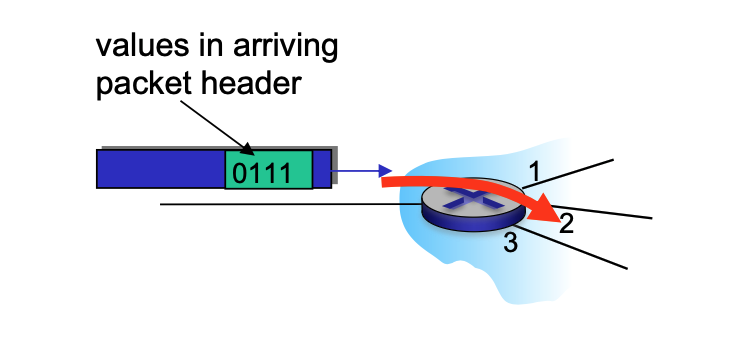
Data Plane
- Local Function: This is a per-router function.
- Operation: It determines how a datagram arriving on a router's input port is forwarded to the output port based on values in the packet header.
Control Plane
- Network-Wide Logic: It determines the end-to-end path that a datagram follows from the source host to the destination host.
-
Approaches:
-
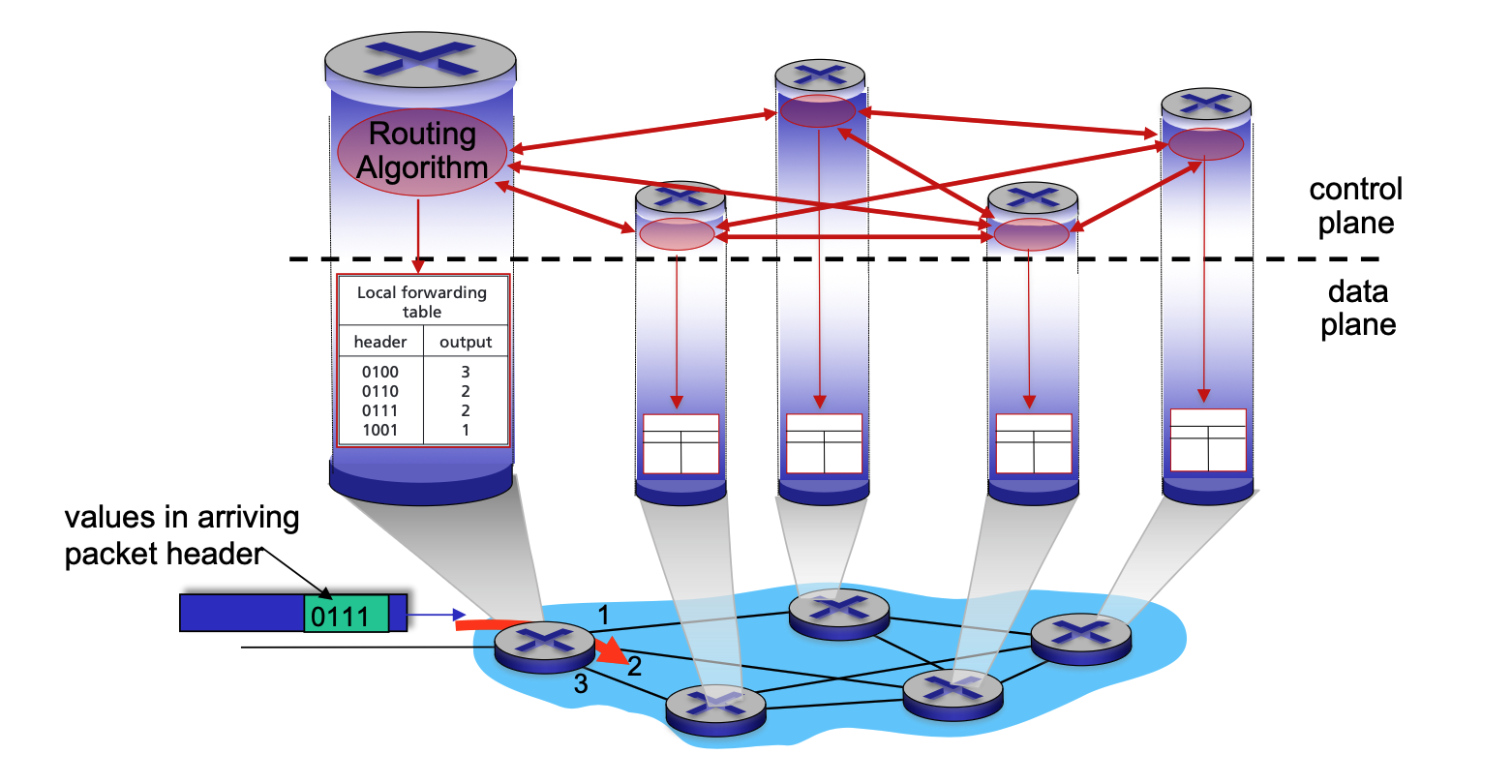
Traditional Routing: Implemented via algorithms running locally in each router.
-
In a per-router control plane setup, the forwarding process strictly follows the local forwarding table, which is itself the result of the routing algorithms.
-
Local Algorithm Components: Every router runs its own individual routing algorithm component.
- Active Interaction: These components interact with each other by exchanging routing messages.
- Topology Sharing: Through these interactions, routers share information about their local links and the status of their neighbors.
- Calculation of Paths: Using the information gathered from its peers, each router independently calculates the best end-to-end path to every possible destination.
- Local Forwarding Table: Once the algorithms "converge" (reach an agreement), each router installs a local forwarding table.
- Header Mapping: This table maps specific packet header values to a dedicated output port.
- Coordinated Movement: Because the routers have interacted to reach a consensus, when a packet with a specific header (e.g., "0111") arrives, each router along the path will have a matching entry that moves the packet toward the correct next hop.
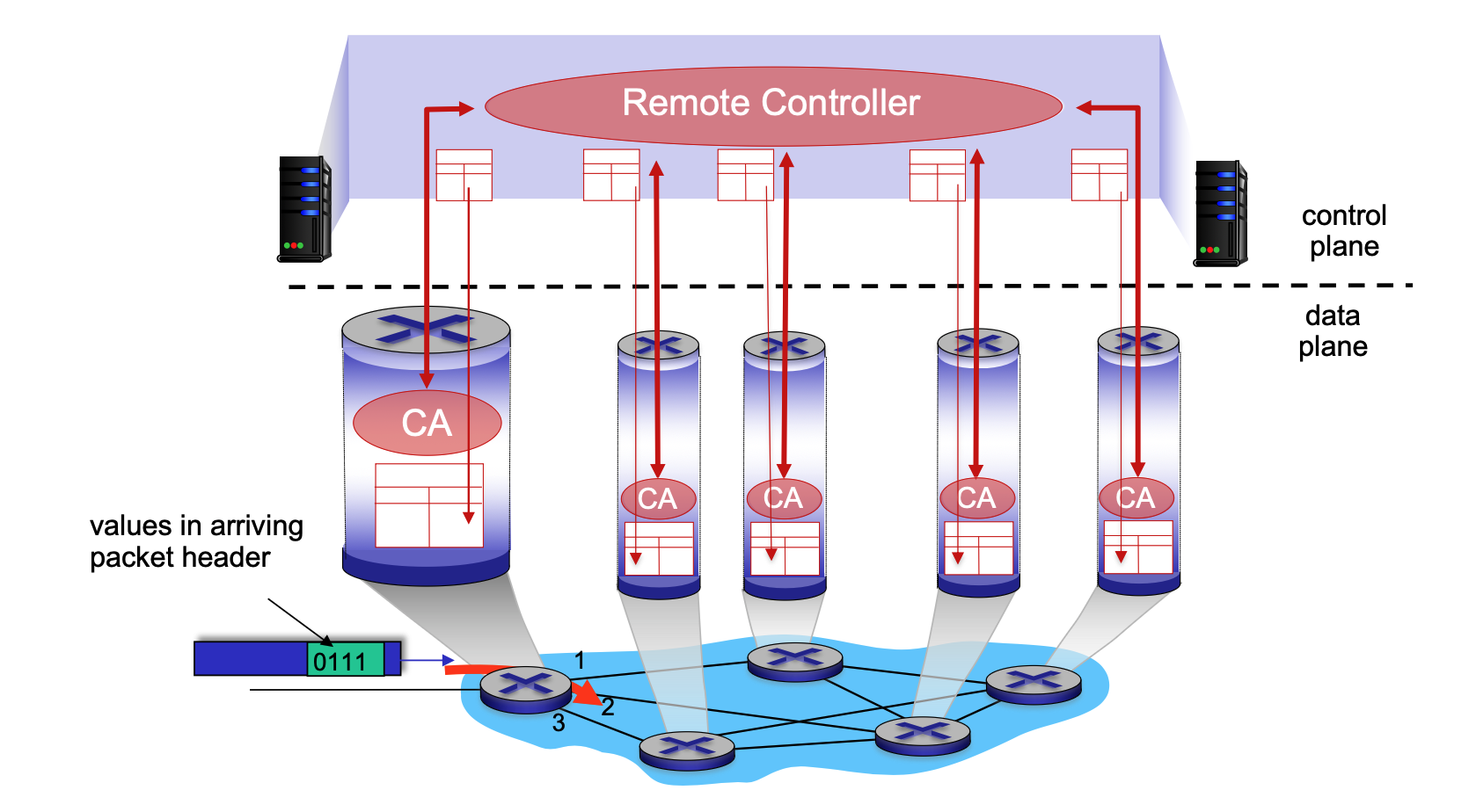
- Software-Defined Networking (SDN): Implemented in remote servers that compute and install forwarding tables in routers.
-
-
Network Service Models
A service model defines the "channel" characteristics for transporting datagrams.
- Individual Datagrams: Services may include guaranteed delivery or delivery within a specific time bound (e.g., < 40 msec).
- Flow of Datagrams: Services may include in-order delivery, guaranteed minimum bandwidth, or restrictions on jitter (inter-packet spacing).
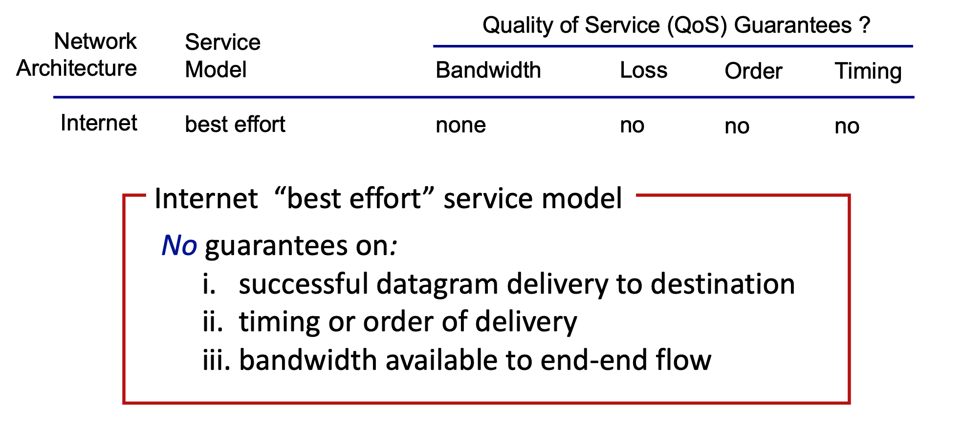
Internet "Best Effort" Service Model
The Internet's architecture follows a "best effort" model, which provides no specific Quality of Service (QoS) guarantees.
- Bandwidth: None guaranteed.
- Loss: No guarantee against packet loss.
- Order: No guarantee that packets arrive in the order sent.
- Timing: No guarantee on the time it takes for delivery.
What’s Inside a Router
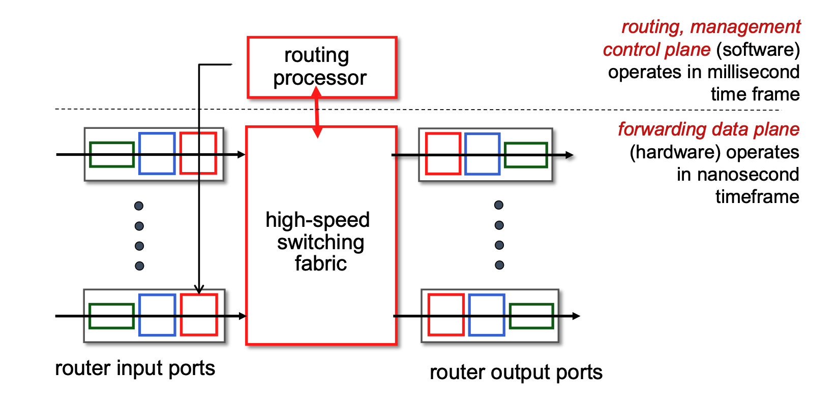
Generic Router Architecture
- Control Plane (Software): Operates on a millisecond time frame. The routing processor handles routing protocols, management, and computes forwarding tables.
- Forwarding Data Plane (Hardware): Operates on a nanosecond time frame. Consists of input ports, a high-speed switching fabric, and output ports.
Input Port Functions & Forwarding
- Pipeline: Datagrams pass through line termination (Physical layer) \(\rightarrow\) Link layer protocol \(\rightarrow\) Lookup, forwarding, and queueing.
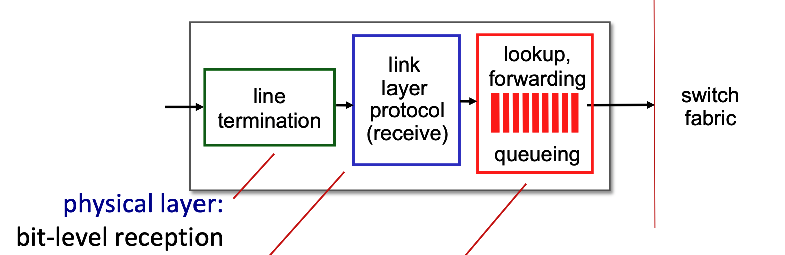
- Functionalities
- Line Termination (Green Block): This module operates at the physical layer. It is responsible for bit-level reception, which means it physically receives the incoming analog signal (such as light pulses over fiber or electrical signals over copper) and converts it into the digital bits (1s and 0s) that the router can understand.
- Link Layer Protocol - Receive (Blue Block): This module operates at the data link layer. It processes the digital bits from the previous step according to the specific protocol used on that incoming link, such as Ethernet. Its main job is to unpack the network-layer datagram from the link-layer frame and check for any frame-level errors.
- Lookup, Forwarding, Queueing (Red Block): This represents the network layer processing within the input port.
- Lookup and Forwarding: This section uses the header fields of the incoming datagram (like the destination IP address) to look up the correct output port in the router's local forwarding table. This is often called a "match plus action" process, and the router aims to perform this lookup at "line speed" (as fast as the data arrives).
- Queueing: If packets arrive and are processed faster than the router's internal switching fabric can move them to the output ports, they are temporarily held in a queue here to prevent them from being dropped.
- Decentralized Switching: Forwarding is done locally at the input port using a "match plus action" forwarding table to achieve processing at "line speed."
- Destination-based forwarding: Traditional forwarding based solely on the destination IP address.
- Generalized forwarding: Forwarding based on any set of header fields.
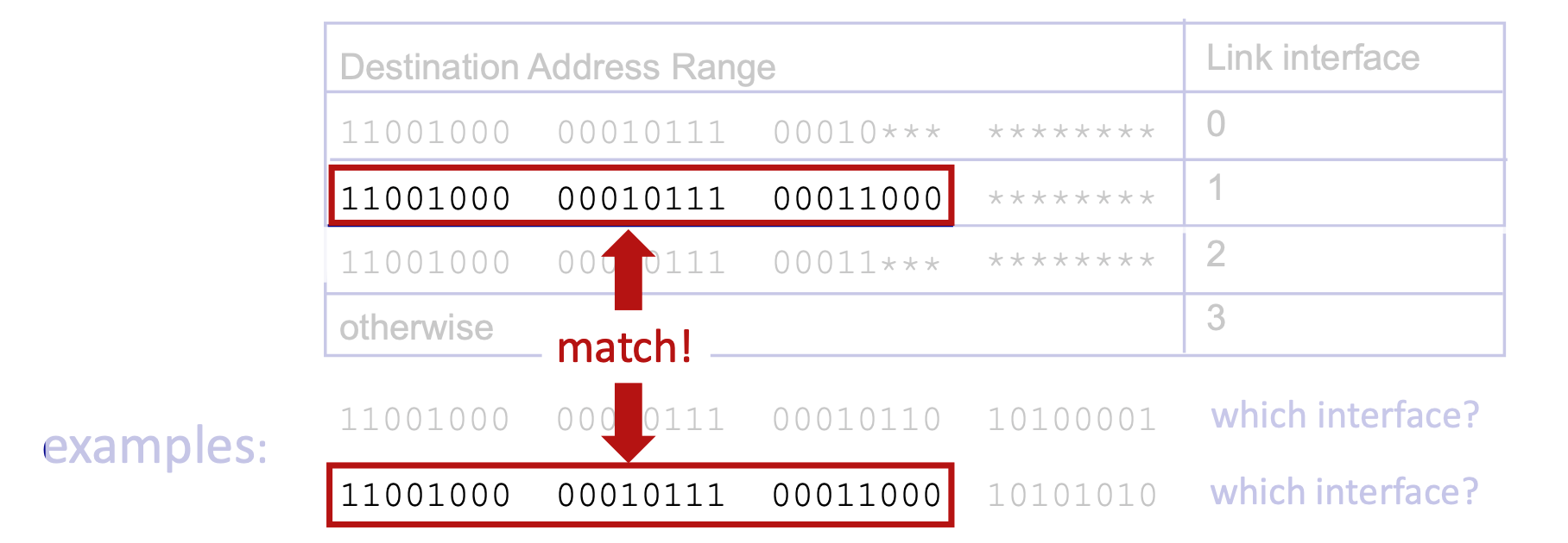
- Longest Prefix Matching: When mapping a destination address to a link interface, the router uses the longest address prefix that matches the destination.
- TCAMs (Ternary Content Addressable Memories): Hardware used to perform longest prefix matching rapidly, retrieving the address in a single clock cycle regardless of table size.
Switching Fabrics & Input Queueing
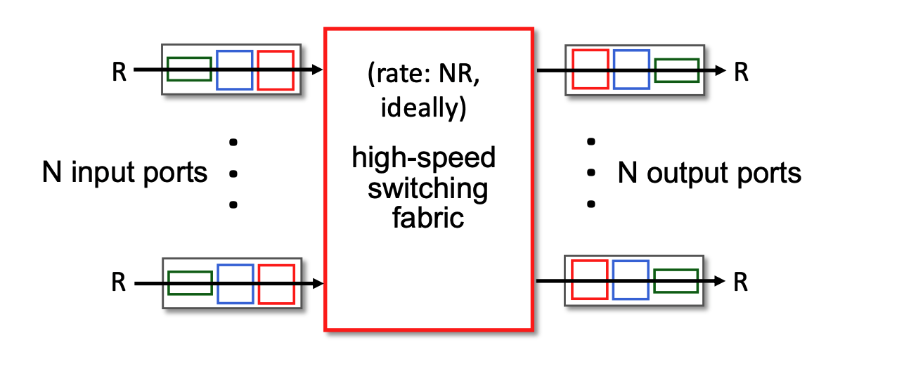
- Switching Fabric: Transfers packets from input links to output links. The ideal switching rate is \(N\) times the line rate (where \(N\) is the number of inputs).
- Switching rate: rate at which packets can be transfer from inputs to outputs
- Line rate (often denoted as \(R\)) refers to the maximum physical transmission speed or capacity of a single incoming or outgoing network link. For example, if a router is equipped with 1 Gigabit Ethernet ports, the line rate for each of those ports is 1 Gbps. It is the absolute fastest speed at which bits can physically arrive at an input port or leave an output port.
- The Bottleneck Risk: If the internal switching fabric can only process data at the speed of one single link (\(R\)), and data arrives on multiple links simultaneously, the router will quickly become overwhelmed, forcing packets to wait in input queues.
- The Ideal Scenario: To prevent these internal traffic jams, the switching fabric's capacity needs to be a multiple of the individual port speed. Ideally, if a router has \(N\) input ports, you want the switching fabric to operate at a rate of \(N×R\) (or \(NR\)).
- This \(NR\) rate ensures that even if every single input port receives a packet at its maximum speed in the exact same microsecond, the internal fabric is fast enough to sweep all of them across to the output ports instantly without any delay.
- Input Queueing: If the switch fabric operates slower than the combined input ports, packets must wait in input queues.
- Queueing delay and loss may occur due to input buffer overflow.
- Combined input ports? To understand this, imagine a router that has 4 input ports, and each port is capable of receiving data at a speed of 1 Gbps (the line rate, R). If a burst of traffic happens and packets arrive at all 4 of those ports at the exact same microsecond, the "combined" incoming data rate is 4 Gbps.
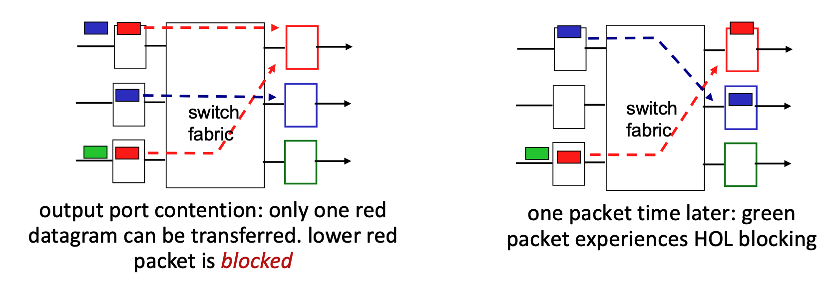
- Head-of-the-Line (HOL) Blocking: A scenario where a queued packet at the front of an input queue prevents other packets behind it from moving forward, even if their target output ports are idle.
Output Port Queueing & Buffering
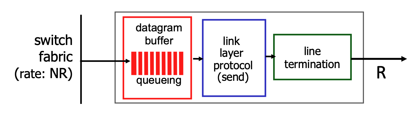
- Output Queueing: Necessary when datagrams arrive from the switching fabric faster than the output link can transmit them. If buffers overflow, datagrams are lost to congestion.
- Buffering and Congestion: If the router's internal switching fabric pushes packets to an output port faster than that port's physical link can transmit them, the packets must wait in a buffer (memory). If this buffer gets completely full, congestion occurs, and datagrams will be lost.
- Buffer Management:
- Drop Policies: Dictate which packet to drop when buffers are full (e.g., tail drop drops the newest arriving packet, priority drop drops based on class).
- When the buffer is full and new packets arrive, the router must use a "drop policy" to decide exactly which packets to throw away.
- Marking: Modifies packets to signal network congestion (e.g., ECN, RED).
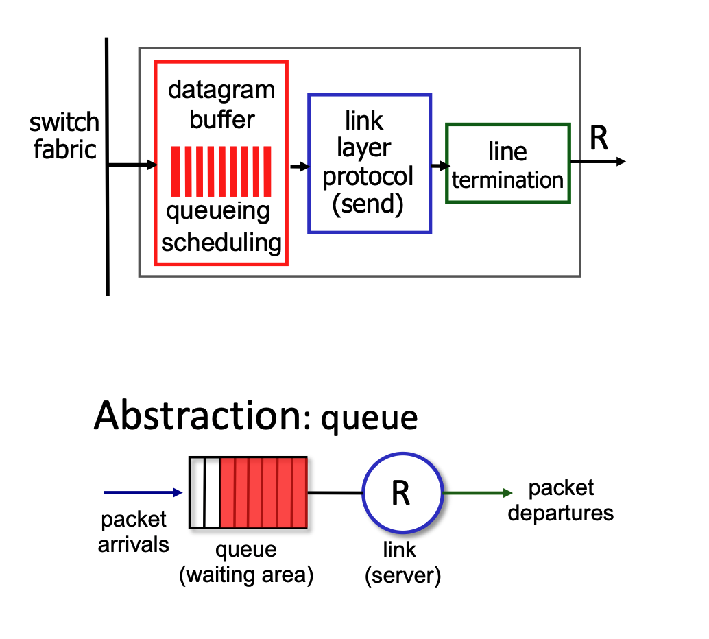
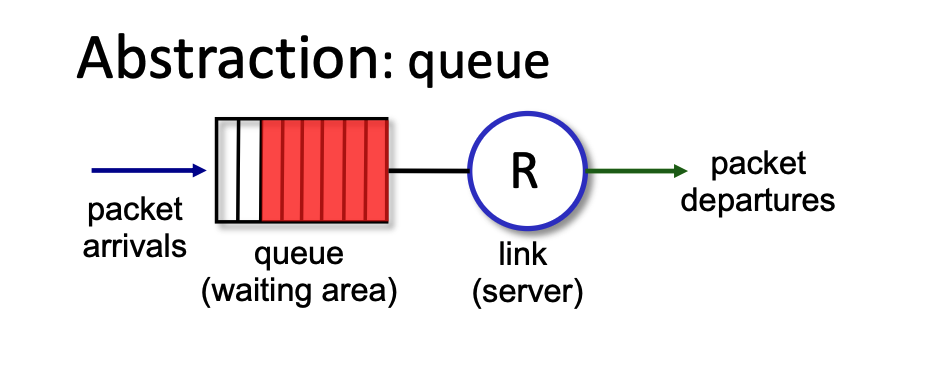
- Scheduling: Determines which queued packet gets transmitted next (e.g., Priority scheduling, which impacts network neutrality).
- For the packets waiting in the buffer, the router must decide the order in which they are transmitted. While it could use a simple first-come, first-served approach, it often uses "priority scheduling". This means certain types of data might get to "skip the line" for better performance, which brings up debates regarding network neutrality.
- Drop Policies: Dictate which packet to drop when buffers are full (e.g., tail drop drops the newest arriving packet, priority drop drops based on class).
- Sizing Buffers:
- RFC 3439 Rule of Thumb: Average buffering should equal a typical Round Trip Time (RTT, e.g., 250 msec) multiplied by the link capacity (\(R\)).
- Trade-off: Too much buffering leads to excessive delays (bufferbloat), harming real-time application performance and TCP responsiveness.
Packet Scheduling Policies
First Come, First Served (FCFS)
- Packet Scheduling: This is the process of deciding which packet to transmit next on a link. Options include FCFS, priority, round robin, and weighted fair queueing.
- FCFS Definition: Packets are transmitted strictly in the order they arrive at the output port. This is also commonly referred to as First-in-first-out (FIFO).
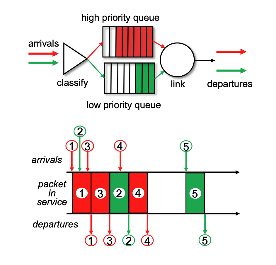
Priority Scheduling
- Classification: Arriving traffic is classified and placed into distinct queues based on its class. Any header field can be utilized for this classification.
- Transmission Order: The system is designed to always send a packet from the highest priority queue that currently has buffered packets waiting.
- Internal Queue Rule: Within a single priority class, packets are processed using standard FCFS.
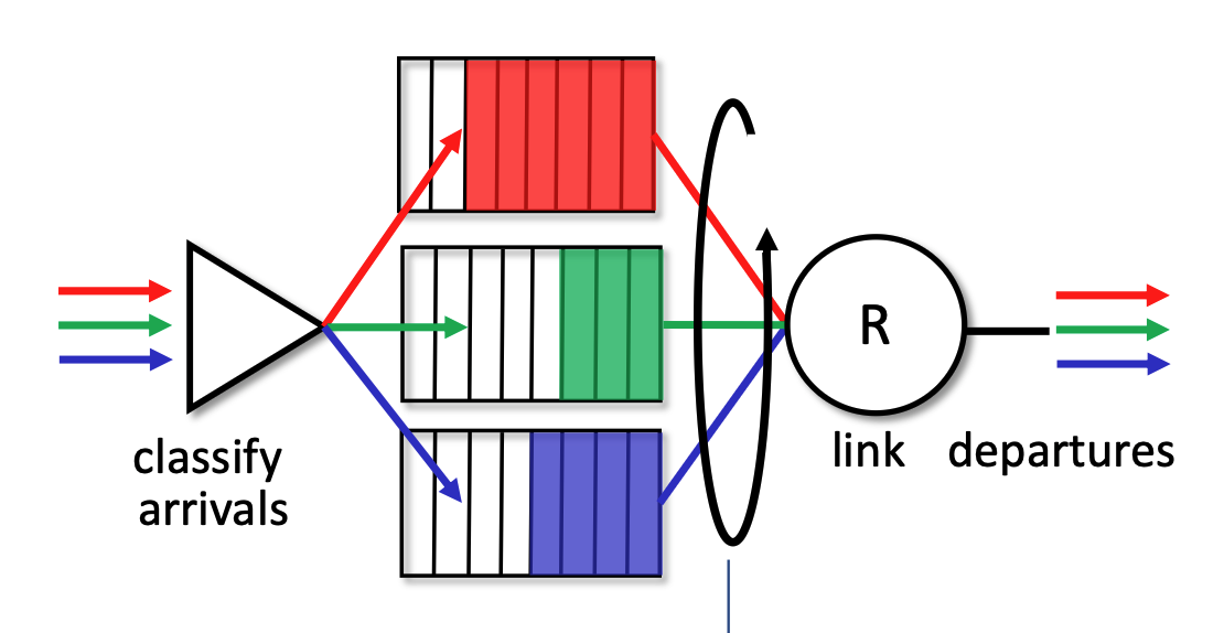
Round Robin (RR)
- Classification: As with priority scheduling, arriving traffic is classified into different queues using header fields.
- Cyclic Scanning: The server repeatedly and cyclically scans all the class queues. It sends exactly one complete packet from each class queue (if one is available) during its turn before moving on to the next.
Weighted Fair Queueing (WFQ)
- Generalization: WFQ operates as a generalized version of Round Robin scheduling.
- Weighted Allocation: Each specific traffic class (\(i\)) is assigned a mathematical weight (\(w_i\)). In each cycle, a class receives a proportionally weighted amount of service defined by the formula \(\frac{w_i}{\sum_j w_j}\).
- Bandwidth Protection: This weighted approach ensures a per-traffic-class minimum bandwidth guarantee, preventing any single queue from being starved.
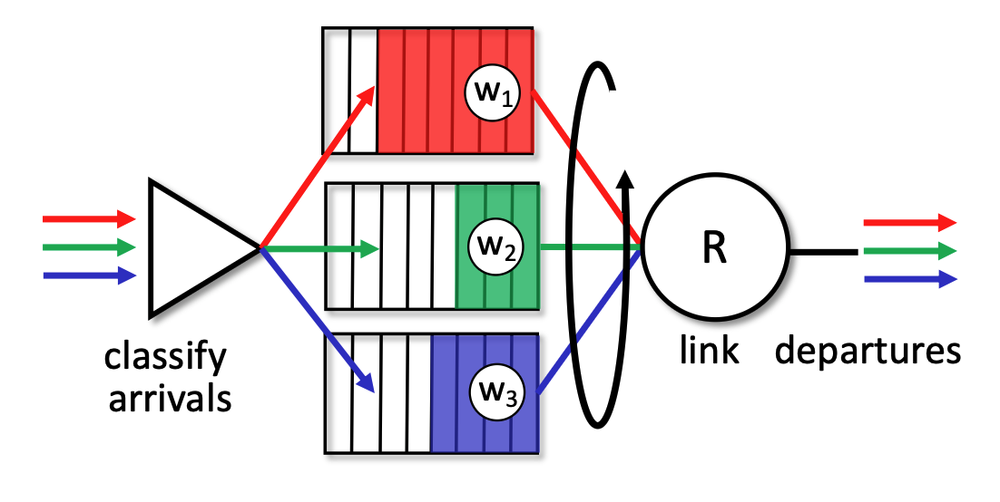
While RR gives everyone an equal turn, WFQ allows network administrators to assign specific weights (\(w_i\)) to different queues. This means WFQ can provide a customized "per-traffic-class minimum bandwidth guarantee". For example, WFQ can guarantee that a video streaming queue gets 70% of the bandwidth while a file download queue gets a guaranteed 30%, rather than the forced 50/50 split of standard Round Robin.
IP: the Internet Protocol
Network Layer Functions in the Internet
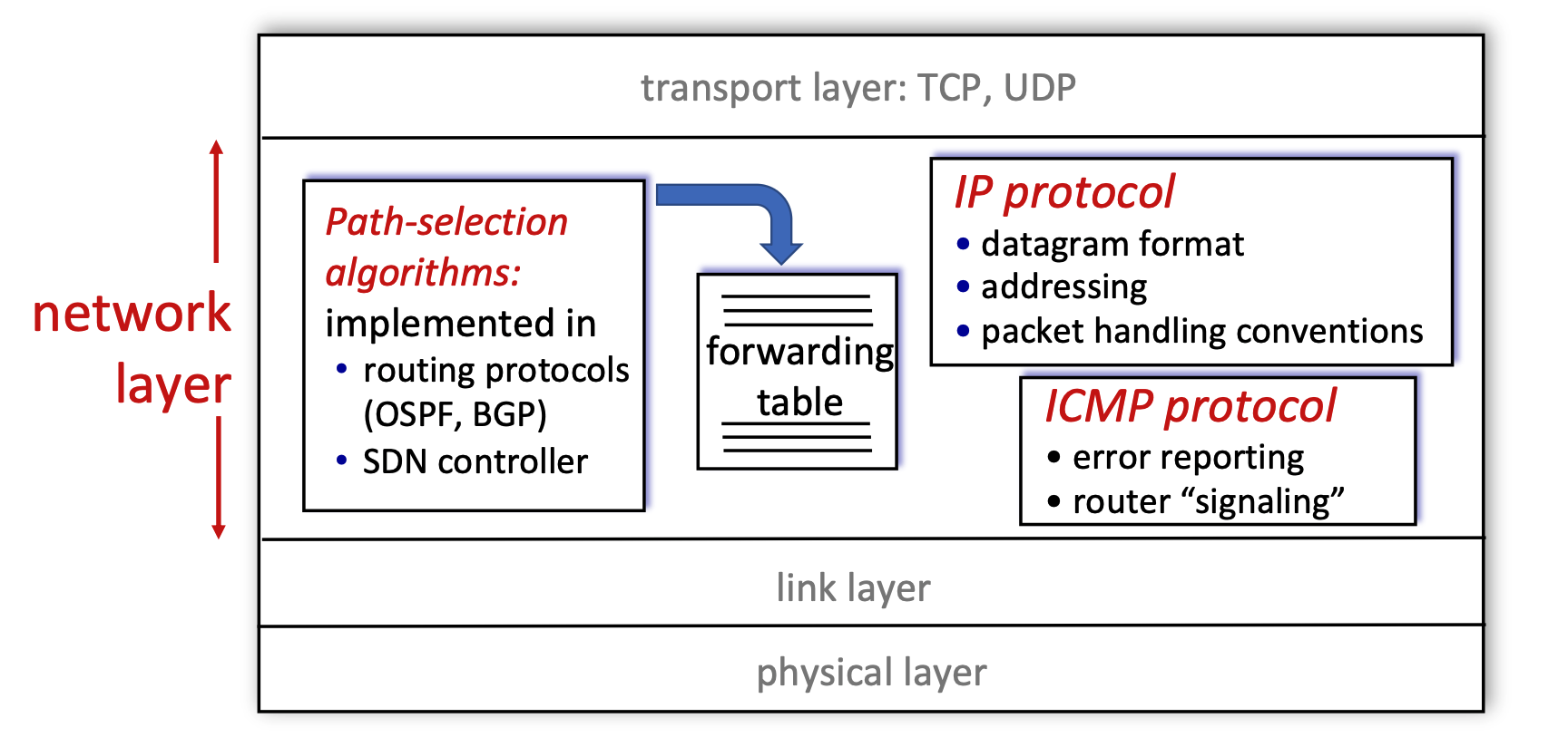
- Layer Position: The network layer operates directly below the transport layer (which handles TCP and UDP) and above the link and physical layers.
- Core Components: The diagram breaks the network layer down into three main functional blocks:
- Path-selection algorithms: These algorithms are implemented in routing protocols (like OSPF or BGP) or via an SDN (Software-Defined Networking) controller. Their primary job is to compute the forwarding table.
- IP Protocol: This is responsible for defining the datagram format, managing addressing, and establishing packet handling conventions.
- ICMP Protocol: The Internet Control Message Protocol handles error reporting and router-to-router "signaling".
IP Datagram Format
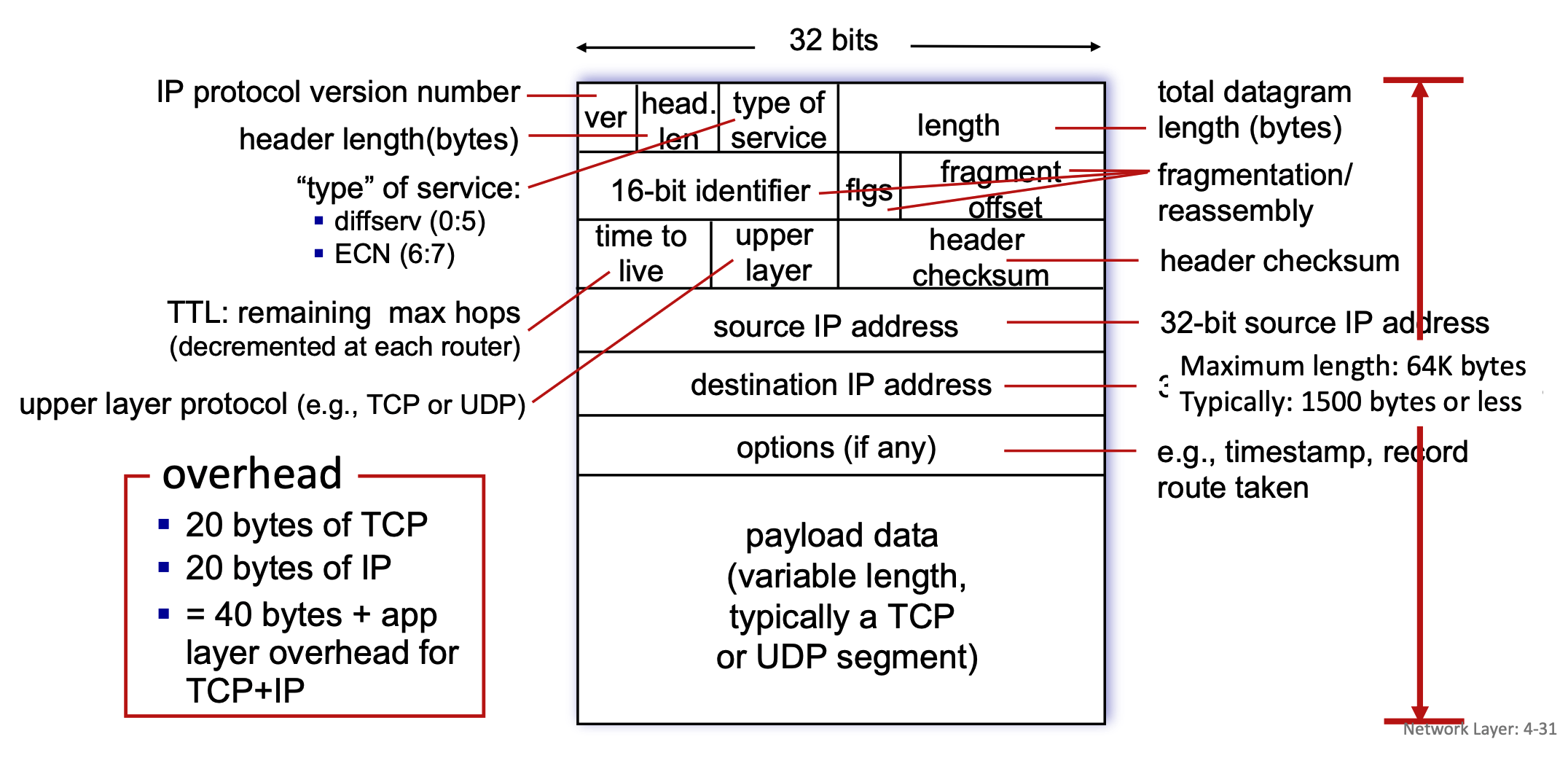
- Structure: An IP datagram consists of a header and a payload, organized in 32-bit (4-byte) rows.
- Header Fields:
- ver: Indicates the IP protocol version number.
- head. len: Specifies the header length in bytes.
- type of service: Defines the service type, including diffserv (bits 0:5) and ECN for congestion notification (bits 6:7).
- length: Represents the total datagram length in bytes. While the maximum theoretical length is 64K bytes, it is typically 1500 bytes or less in practice.
- 16-bit identifier, flgs (flags), fragment offset: These three fields are exclusively used for the fragmentation and reassembly of the datagram.
- time to live (TTL): Indicates the remaining maximum hops the packet can take; this number is decremented by each router it passes through to prevent infinite loops.
- upper layer: Identifies the upper layer protocol of the payload, such as TCP or UDP.
- header checksum: Used for error-checking the header.
- 32-bit source IP address & 32-bit destination IP address: The sender and receiver network addresses.
- options (if any): Can include additional instructions like timestamps or a record of the route taken.
- Payload: The variable-length payload data typically contains a TCP or UDP segment.
- Overhead: A standard packet carries 20 bytes of TCP overhead and 20 bytes of IP overhead (without options, resulting in 40 bytes of total overhead plus any application layer overhead.)
- What MSS Includes: MSS (Maximum Segment Size) represents the maximum amount of application payload data that a single TCP segment can carry. It only includes this actual data; it strictly excludes any network-level or transport-level headers.
- The Relationship to MTU: The slides define MTU (Maximum Transfer Unit) as the "largest possible link-level frame". MSS is directly constrained by this MTU. MTU = max size of a whole packet on a link
- The Calculation: A standard packet has 20 bytes of IP header overhead and 20 bytes of TCP header overhead, resulting in 40 bytes of total basic overhead. Because MSS only measures the payload, it is calculated by taking the network's MTU and subtracting those headers (MSS = MTU - IP Header - TCP Header).
- Data Unit in Network Layer
- Datagram: This is the technically precise term for the unit of data at the network layer, specifically when talking about the Internet Protocol (IP).
- Packet: This is a widely accepted, more generic term for a formatted block of data traversing a network.
IP Fragmentation and Reassembly
- The MTU Problem: Network links have a Maximum Transfer Unit (MTU), which dictates the largest possible link-level frame that can be transmitted. Because networks are heterogeneous, different link types have varying MTU sizes.
- The MTU Limit: The Maximum Transfer Unit (MTU) specifically dictates the maximum size of the payload that the link layer can carry. In this context, the link layer's payload is the entire IP datagram (IP Header + TCP Header + Application Data).
- The Link Layer Frame: The link layer takes that complete IP datagram (which is strictly limited by the MTU size) and wraps it by adding its own Link Layer Header at the front and a Trailer at the end.
- Link-layer headers are NOT inside the MTU!
- Fragmentation Process: If a router receives a large IP datagram that exceeds the MTU of the outgoing link, the datagram is divided, or "fragmented," into several smaller datagrams.
- Reassembly: These fragments traverse the network independently and are "reassembled" back into the original large datagram only when they reach the final destination host, not at intermediate routers.
- Tracking: The IP header bits (specifically the identifier, flags, and offset fields mentioned in the datagram format) are used to identify related fragments and order them correctly during reassembly.
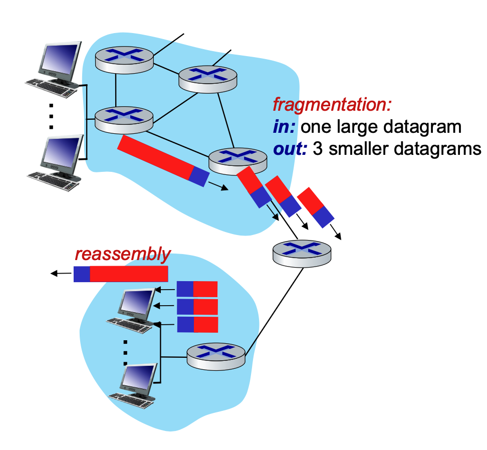
When a router encounters an IP datagram that is larger than the Maximum Transfer Unit (MTU) of the outgoing network link, it must divide, or "fragment," that large datagram into several smaller ones.
To ensure the final destination can put these pieces back together correctly, the router copies and modifies specific fields in the IP header for each new fragment.
It is also important to remember the final rule of this process: these smaller datagrams are "reassembled" only at the final destination host. The intermediate routers in the network simply forward the fragments as independent packets.
IP Fragmentation and Reassembly
When an IP datagram is too large to pass through a network link because of a smaller Maximum Transmission Unit (MTU), it must be fragmented into smaller packets. Reassembly only happens at the final destination host, not at the routers in between.
How to Calculate Fragmentation
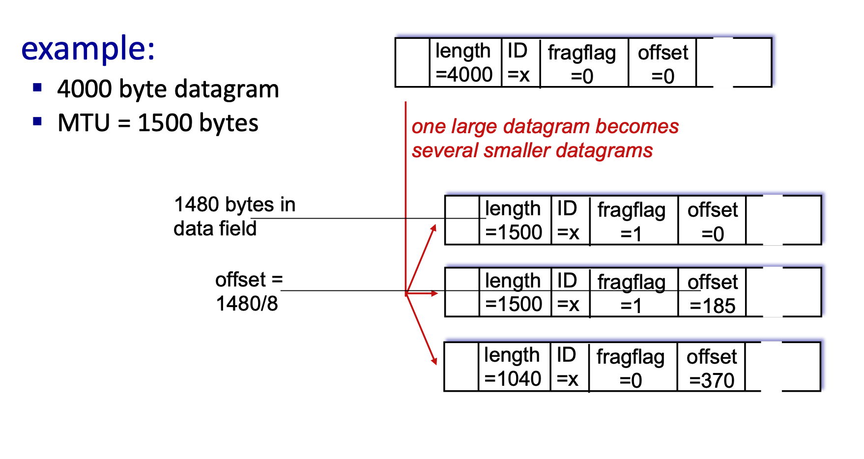
Let's break down the math using above example of a 4000-byte datagram being sent over a link with a 1500-byte MTU.
- Understand the Headers: A standard IPv4 header is 20 bytes.
- Original Datagram Length = 4000 bytes.
- Original Payload (Data) = \(4000 - 20 = 3980\) bytes.
- Determine the Fragment Payload Size: The MTU is 1500 bytes. Subtract the 20-byte IP header that must be attached to every fragment.
- Max Payload per fragment = \(1500 - 20 = 1480\) bytes.
- Note: The fragment payload size must be a multiple of 8 because the offset field specifies lengths in 8-byte blocks. Since 1480 is divisible by 8, we can use it.
- Calculate Each Fragment:
- Fragment 1:
- Data: First 1480 bytes.
- Length: \(1480 + 20 = 1500\).
- ID:
x(stays the same for all fragments to identify them as a group). - Fragflag (More Fragments):
1(Yes, more are coming). - Offset:
0(Starts at the beginning).
- Fragment 2:
- Data: Next 1480 bytes.
- Length: \(1480 + 20 = 1500\).
- ID:
x. - Fragflag:
1(More are coming). - Offset: Calculated as \(\frac{Previous\_Data}{8}\). So, \(\frac{1480}{8} = 185\).
- Fragment 3 (Final Fragment):
- Data: Remaining bytes. Total was 3980. We sent \(1480 + 1480 = 2960\). Remaining = \(3980 - 2960 = 1020\) bytes.
- Length: \(1020 + 20 = 1040\).
- ID:
x. - Fragflag:
0(This is the last fragment). - Offset: \(\frac{1480 + 1480}{8} = 370\).
- Fragment 1:
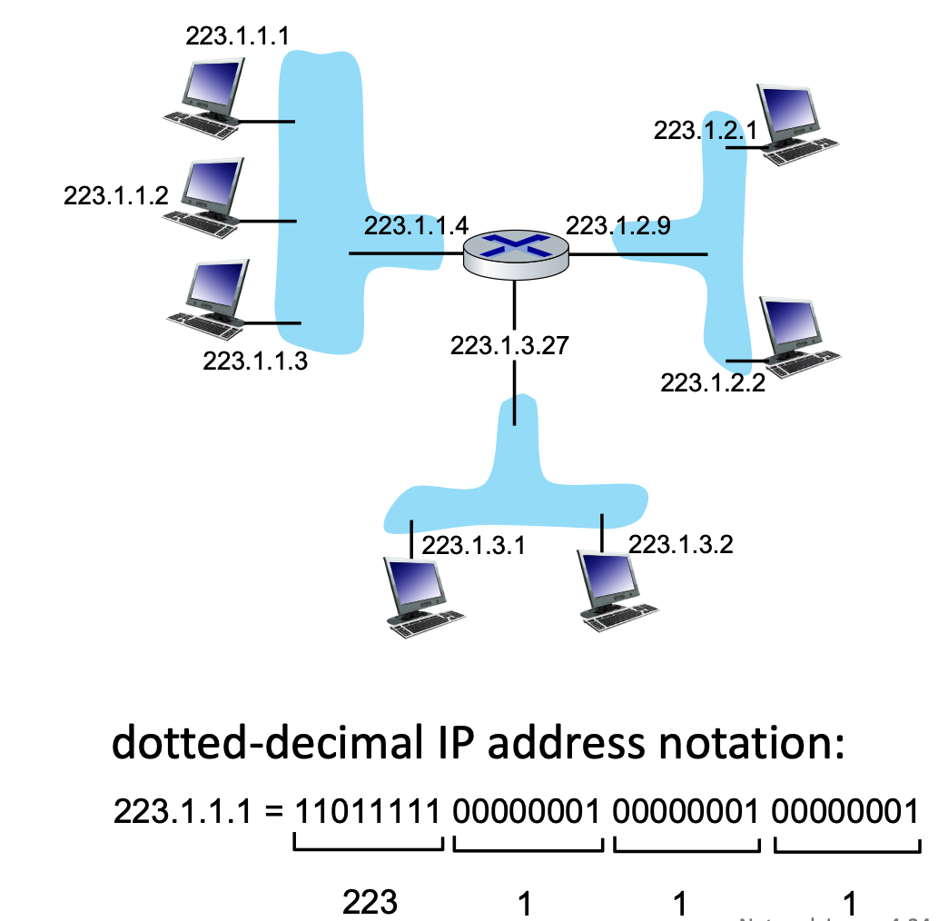
IP Addressing and Interfaces
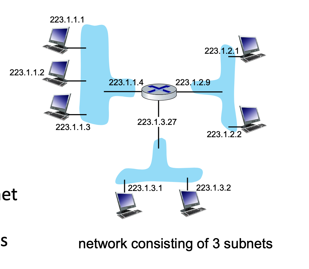
- IP Address: A 32-bit identifier for a host or router interface, typically written in dotted-decimal format (e.g.,
223.1.1.1). - Interface: The actual physical connection point between a device (host/router) and the physical link.
- Routers have multiple interfaces to connect different networks.
- Hosts usually have one or two (e.g., an Ethernet port and a WiFi card).
- wired Ethernet interfaces connected by Ethernet switches
- wireless WiFi interfaces connected by WiFi base station
Subnets and CIDR
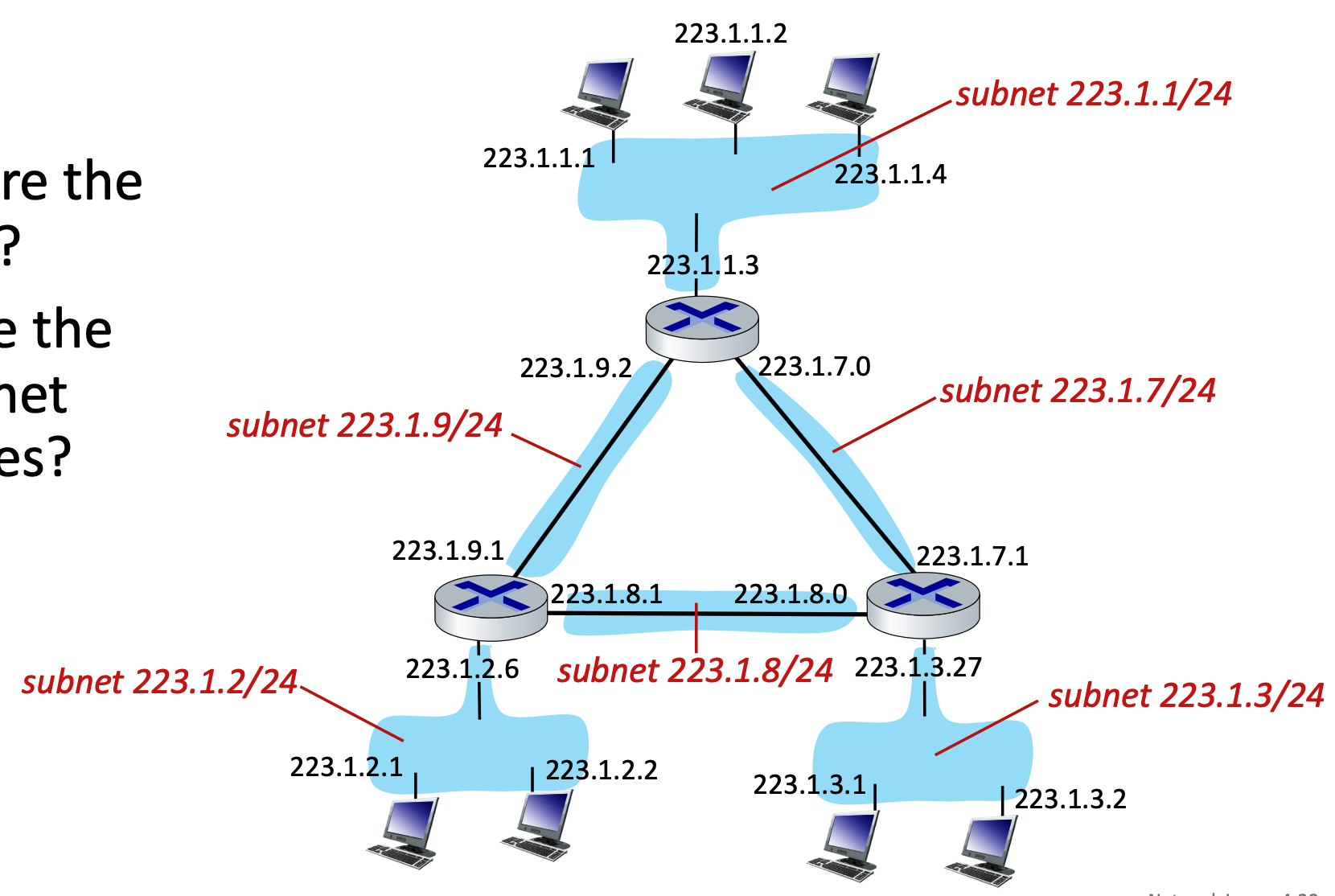
A subnet is a grouping of device interfaces that can physically communicate with one another without routing traffic through an intervening router. Think of them as isolated "islands" of networks.
Subnet Structure and CIDR Notation
IP addresses are divided into two parts: the Subnet Part (high-order bits) and the Host Part (low-order bits).
CIDR (Classless InterDomain Routing) uses the notation a.b.c.d/x to indicate the subnet mask.
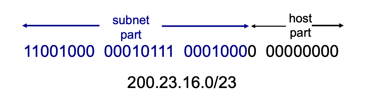
- The
/xdefines exactly how many bits (from left to right) make up the network/subnet portion.- Instead of being locked into predefined classes, a network administrator can draw the line between the "subnet part" and the "host part" wherever they want, using any number of bits from 0 to 32.
- Because an IPv4 address is exactly 32 bits long, the remaining bits (\(32 - x\)) are allocated for the host portion.
Calculating Available IP Addresses
If you are given a subnet like /x, you can calculate the total number of IP addresses available in that network.
- Formula: Total IPs = \(2^{32-x}\)
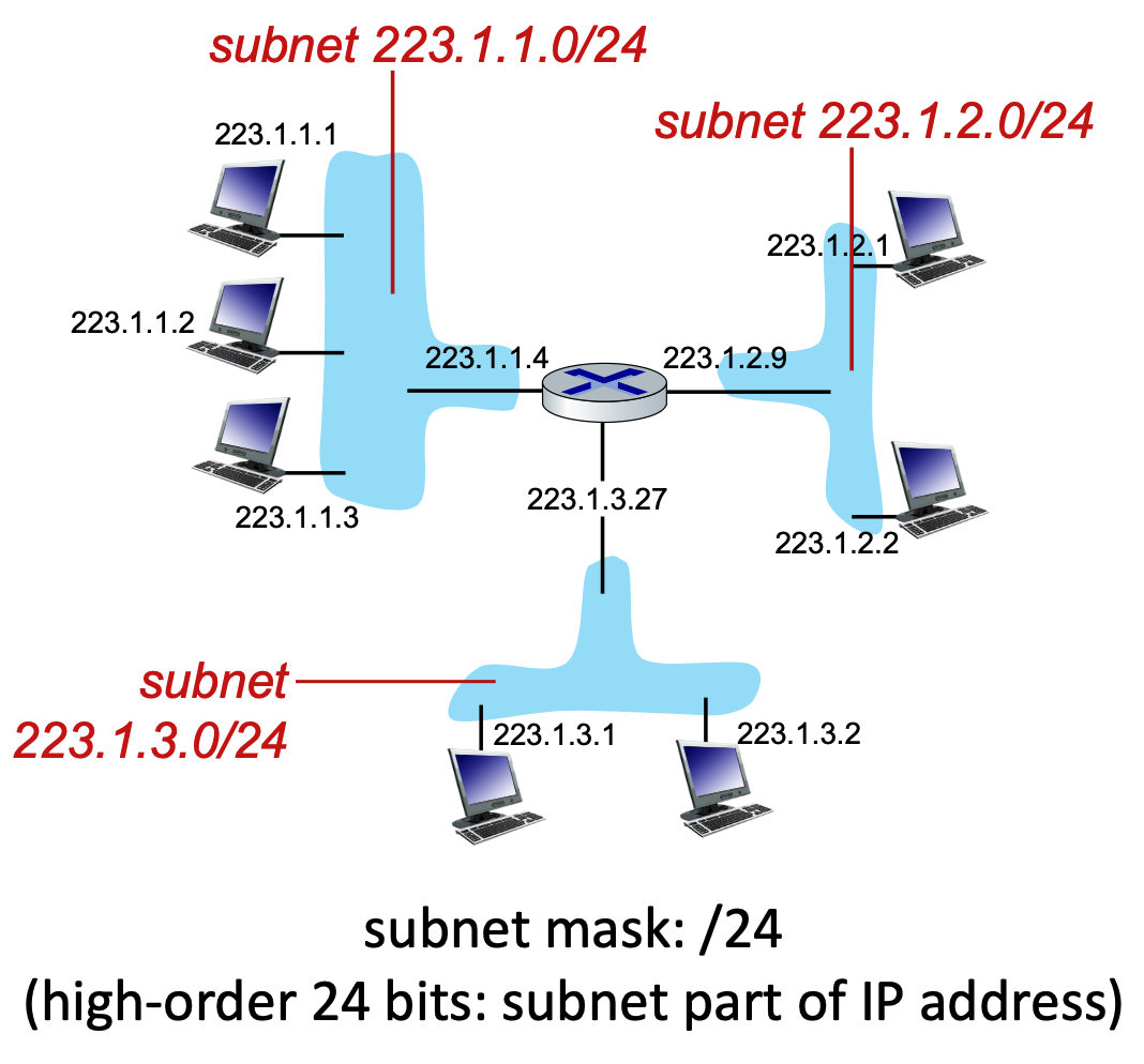
- Example: For a subnet of
223.1.3.0/24:- Network bits = \(24\)
- Host bits = \(32 - 24 = 8\)
- Total IP addresses = \(2^{8} = 256\)
- In real-world networking, the usable number of hosts is always \(2^{32-x} - 2\). The first address (all host bits are 0) is reserved as the Network ID, and the last address (all host bits are 1) is reserved as the Broadcast address.
DHCP: Dynamic Host Configuration Protocol
DHCP is an application-layer protocol that allows a host to automatically obtain an IP address (and other network configurations like the default gateway and DNS servers) when it joins a network.
The DHCP "DORA" Process
When a device connects to a network, it goes through a four-step sequence to get an IP address:
- Discover (Optional): The new host broadcasts a
DHCP discovermessage to the entire local subnet to find a DHCP server. - Offer (Optional): Any listening DHCP servers respond with a
DHCP offermessage, proposing an available IP address. - Request: The host selects one of the offers and broadcasts a
DHCP requestmessage, formally asking to lease that specific IP address. - Acknowledge (Ack): The server finalizes the lease and sends a
DHCP ackmessage. The host can now use the IP address.
Key Benefits of DHCP:
- Addresses are leased, not permanently assigned, allowing for the reuse of IPs when devices disconnect.
- Ideal for mobile users constantly joining and leaving different networks.
- Eliminates manual, hard-coded IP configuration by system administrators.
DHCP Process: Client-Server Scenario and Wireshark Details
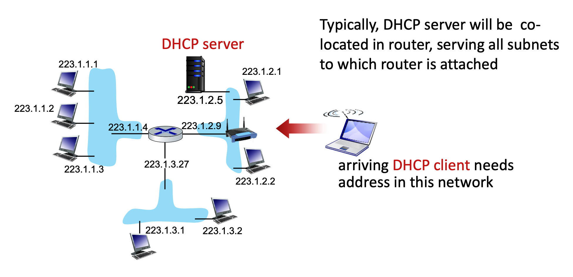
When a new client arrives on a network, it needs an IP address. Typically, a DHCP server is co-located within the network's router to serve all attached subnets.
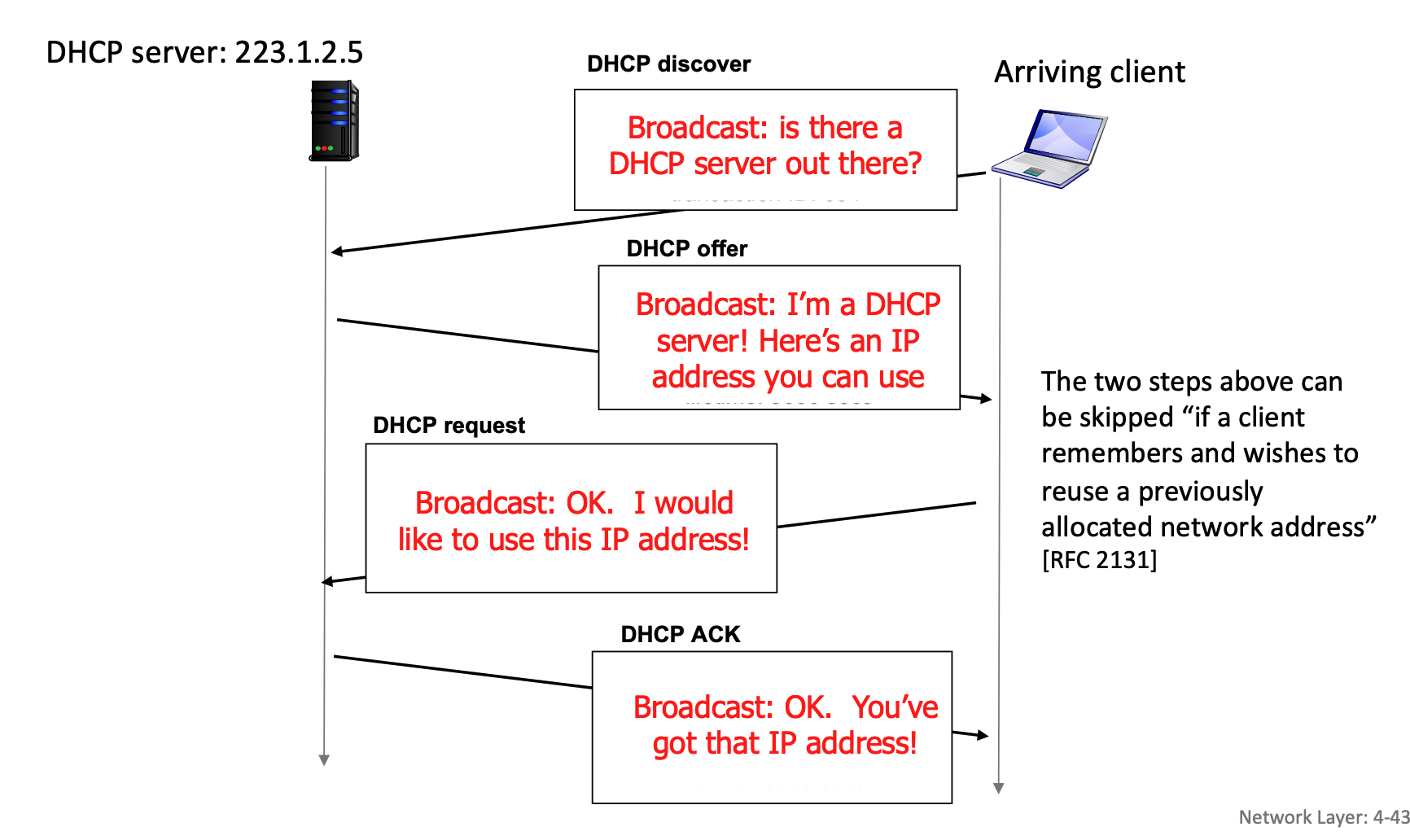
The process uses a series of messages:
- DHCP discover: The client broadcasts a message asking if a DHCP server is out there.
- DHCP offer: The server responds with a broadcast offering an IP address.
- DHCP request: The client broadcasts a message stating it would like to use the offered IP address.
- DHCP ACK: The server broadcasts an acknowledgment, finalizing the IP address allocation.
- Note: The first two steps (discover and offer) can be skipped if a client remembers and wants to reuse a previously allocated address.
Here is how the interaction plays out when there are multiple DHCP servers on a network:
- The Broadcasted Discover: The client shouts out to the entire network, "Is there a DHCP server out there?".
- Multiple Offers: If there are multiple DHCP servers, each of them might hear the discover and send back their own
DHCP offermessage, proposing a different available IP address from their respective pools. - The Broadcasted Request (The Key Step): The client receives these offers but only needs one IP address. It chooses one of the offers (usually the first one it receives). It then sends a
DHCP requestmessage saying, "OK. I would like to use this IP address!". Crucially, this request is also sent as a network-wide broadcast. - The "Ah, I wasn't chosen" moment: Because the request is a broadcast, every DHCP server on the network hears it. Inside that request message, the client includes a specific "Server Identifier" (Option 54) that names the exact server it selected.
- The chosen server sees its own ID, knows its offer was accepted, and prepares the final
DHCP ACKto finalize the lease. - The other servers read the request, see that a different server's ID was chosen, and immediately know their offers were rejected. They then retract their proposed IP addresses and put them back into their pool of available addresses for the next device that comes along.
- The chosen server sees its own ID, knows its offer was accepted, and prepares the final
In real-world, the DHCP server will often ping an IP address right before offering it (before DHCP offer is sent) to make absolutely sure no other device is secretly using it. Additionally, once the client receives its final DHCP ACK, it might broadcast a special message called a "Gratuitous ARP" to double-check that no one else on the local link claims to own that newly assigned IP address.
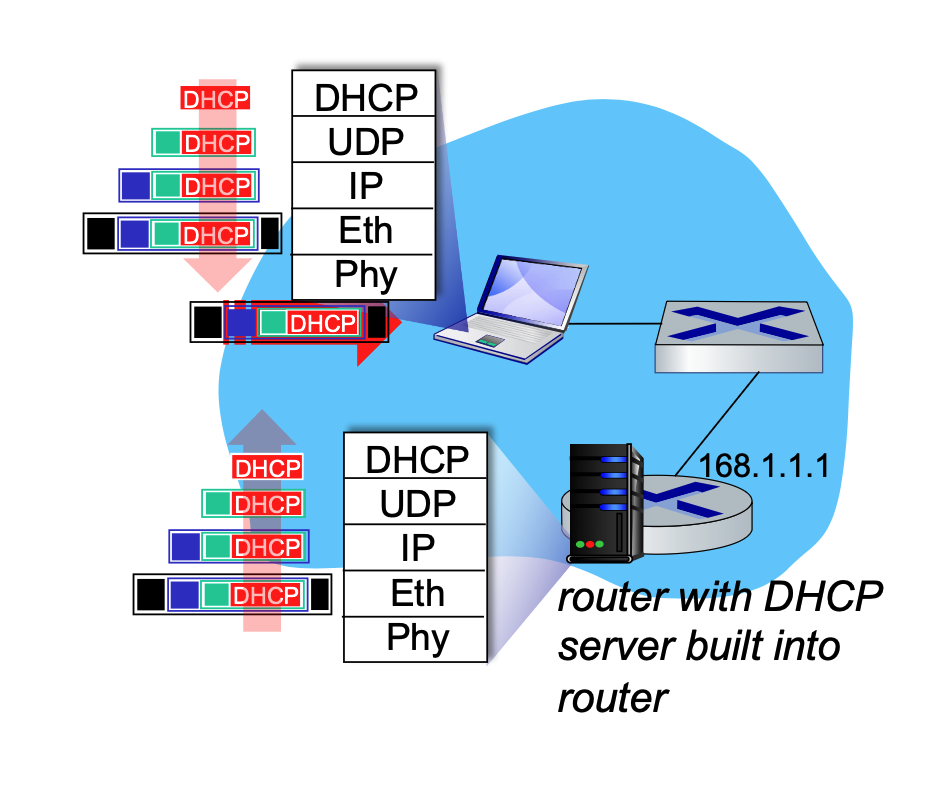
During this process, the DHCP REQUEST message is encapsulated inside a UDP segment, which is encapsulated in an IP datagram, and finally encapsulated in an Ethernet frame. The server receives this, demultiplexes the Ethernet frame up to the IP layer, then UDP, and finally to the DHCP application. After allocating the address, the server formulates the DHCP ACK and forwards it back to the client.
Wireshark captures of DHCP traffic (Boot Request and Boot Reply) show the breakdown of these messages, revealing client MAC addresses, requested IP addresses, and specific DHCP options like Subnet Mask (Option 1), Router (Option 3), and Domain Name Server (Option 6).
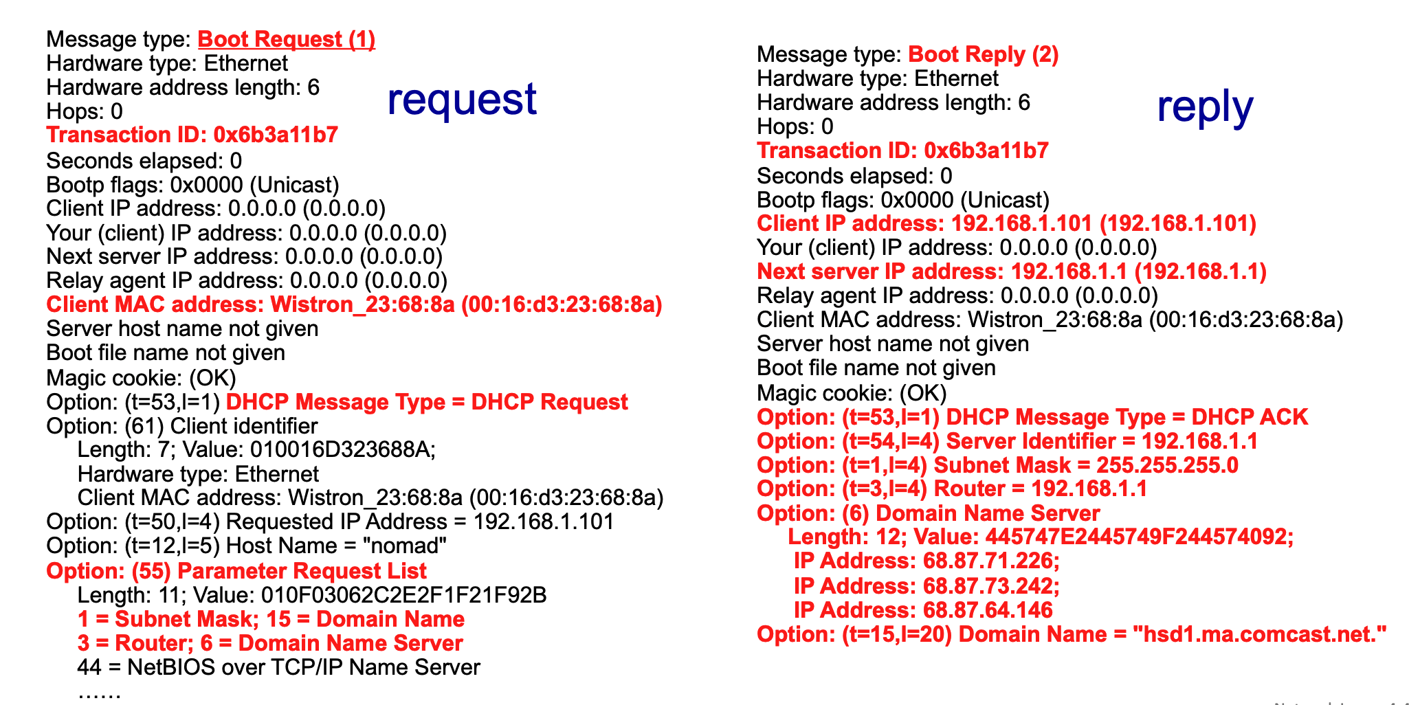
Breakdown of DHCP Wireshark Output
The above image provides a side-by-side view of a DHCP exchange captured via Wireshark on a home Local Area Network (LAN). The red text highlights the most critical fields in the client's request and the server's subsequent reply.
The Client's Request (Left Side)
- Message type: Boot Request (1): This indicates that the message is originating from the client, asking the network for configuration data. (Note: DHCP evolved from an older protocol called BOOTP, which is why Wireshark labels it "Boot Request").
- Transaction ID: 0x6b3a11b7: A unique hexadecimal identifier generated by the client for this specific request session. The server will use this exact ID in its reply so the client knows the message is meant for them.
- Client MAC address: The physical hardware address of the requesting device (
Wistron_23:68:8aor00:16:d3:23:68:8a). Since the client doesn't have an IP address yet, this is its only unique identifier on the local network. - Option: (t=53,l=1) DHCP Message Type = DHCP Request: This specific option field clarifies exactly what phase of the DHCP process this packet represents—in this case, the client formally requesting an IP address.
- Option: (55) Parameter Request List: This is the client giving the server a "wishlist" of extra network configurations it needs besides just an IP address. The red notes below it show the specific items requested:
1 = Subnet Mask15 = Domain Name3 = Router(The default gateway)6 = Domain Name Server(DNS)
The Server's Reply (Right Side)
- Message type: Boot Reply (2): This indicates the packet is a response coming back from the DHCP server to the client.
- Transaction ID: 0x6b3a11b7: Notice this matches the client's request exactly, linking the two messages together.
- Client IP address: 192.168.1.101: This is the server officially offering/assigning this specific IP address to the requesting client.
- Next server IP address: 192.168.1.1: This identifies the IP address of the DHCP server itself (which is typically also the local router on a home network).
- Option: (t=53,l=1) DHCP Message Type = DHCP ACK: This signifies that the server is Acknowledging (ACK) the client's request and finalizing the lease of the IP address.
- Fulfilling the Parameter Request List: The remaining red options show the server providing the exact configuration data the client asked for in its "wishlist":
- Option: (t=54,l=4) Server Identifier = 192.168.1.1: Re-confirming the DHCP server's IP.
- Option: (t=1,l=4) Subnet Mask = 255.255.255.0: Telling the client how to divide the network and host portions of the IP.
- Option: (t=3,l=4) Router = 192.168.1.1: Telling the client where to send traffic destined for the outside internet.
- Option: (6) Domain Name Server: The server provides three different IP addresses (
68.87.71.226,68.87.73.242,68.87.64.146) for DNS servers that the client should use to resolve website names. - Option: (t=15,l=20) Domain Name = "hsd1.ma.comcast.net.": The local domain name assigned by the ISP (Comcast in this example).
Broadcast vs. Unicast
To understand how DHCP communicates, it is important to distinguish between broadcast and unicast:
-
Broadcast: This is a one-to-all communication method. A message is sent to every device on the local network. In DHCP, the initial Ethernet frame is broadcasted using the destination MAC address
FFFFFFFFFFFF. This is necessary because the arriving client does not yet have an IP address and doesn't know the IP address of the DHCP server.When a device first connects to a network, it faces a classic "chicken-and-egg" problem. It needs to send a message to the DHCP server to ask for an IP address, but it cannot send a direct (unicast) message for two main reasons:
- It does not know who or where the server is: The client does not know the IP address or the physical MAC address of the DHCP server on the local network.
- It does not have its own identity yet: The client itself does not have a valid IP address to use as a source address (it temporarily uses
0.0.0.0as its IP).
Because the client cannot direct a message to a specific, known destination, it has to "shout" its request to every device on the local network (LAN) by asking, "Is there a DHCP server out there?".
At the hardware level (the Ethernet layer), this "shout" is accomplished using a broadcast address. By setting the destination MAC address to
FFFFFFFFFFFF(which is all binary 1s), the network switch knows it must forward this specific frame to every single connected device.Every machine on the LAN receives this frame. Normal devices (like other laptops or printers) will look at the encapsulated data, realize they are not DHCP servers, and simply drop the packet. However, the router running the DHCP server will receive the broadcast frame, demultiplex the data up through the IP and UDP layers, recognize it as a DHCP request, and begin the process of assigning an address.
-
Unicast: This is a one-to-one communication method, directed from a single sender to a single, specific receiver. While the standard DHCP DORA process heavily relies on broadcast, Wireshark captures sometimes show "Unicast" flags (e.g.,
Bootp flags: 0x0000 (Unicast)), indicating that specific phases or server configurations can utilize unicast replies once the client's MAC address is identified by the server.- If the client already has an IP and is renewing its lease, it can receive unicast.
DHCP: More Than Just IP Addresses
DHCP is highly versatile. Beyond just assigning a temporary IP address, it configures several critical network parameters for the client:
- The address of the first-hop router (the default gateway) for the client.
- The name and IP address of the network's DNS server.
-
The network mask, which tells the client which portion of the address belongs to the network and which belongs to the host.
Think of an IP address like a physical street address. It is made of two distinct parts:
- The Network Portion (The Street Name): This identifies the specific neighborhood or "subnet" the device lives in. All devices that can talk to each other directly (without passing through a router) share this exact same network portion (the high-order bits).
- The Host Portion (The House Number): This uniquely identifies the specific device (laptop, phone, etc.) on that street using the remaining low-order bits.
Because an IP address is just a continuous string of 32 binary bits (1s and 0s), a computer does not automatically know where the "street name" ends and the "house number" begins.
This is exactly what the Network Mask (or Subnet Mask) does. It acts as a template that overlays the IP address to tell the computer exactly where to draw the dividing line.
How the Mask Works
Look at the Wireshark example above where the DHCP server assigned the Subnet Mask
255.255.255.0.If we translate that decimal mask into binary, it looks like this:
11111111.11111111.11111111.00000000- The 1s represent the Network Portion: The first 24 bits are all 1s. This tells the computer, "The first 24 bits of the IP address are the network part".
- The 0s represent the Host Portion: The last 8 bits are all 0s. This tells the computer, "The remaining 8 bits are the unique host part."
Connecting it to CIDR Notation
When a network is written as
223.1.3.0/24, that/24is just a shorthand way of writing the network mask. It means "the mask has 24 ones in a row", which translates exactly to255.255.255.0.Similarly, if a network is defined as
200.23.16.0/23, the mask would have exactly 23 ones, leaving 9 zeroes for the host portion.By giving the client this mask during the DHCP process, the client instantly knows which other IP addresses are on its local network (and can be reached directly) and which ones belong to the outside world (and must be sent to the router).
Network IP Allocation and Route Aggregation
While individual hosts get their IP addresses from DHCP, entire networks must get their subnet blocks from an Internet Service Provider (ISP).
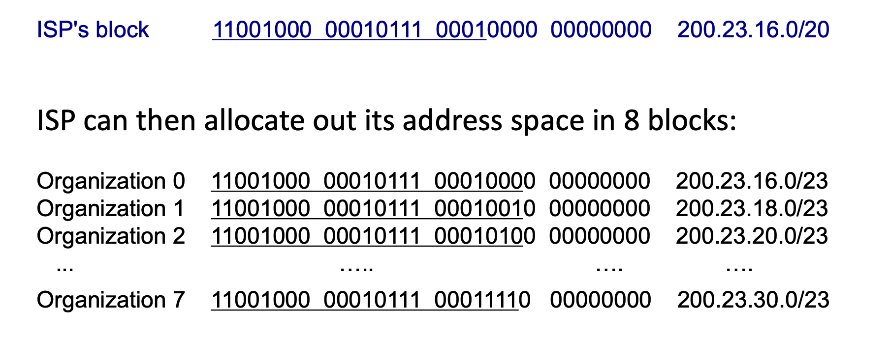
- Subnet Allocation: A network gets its subnet portion by receiving an allocated piece of its ISP's larger address space. For example, an ISP with the block
200.23.16.0/20can divide it into 8 (\(2^{23-20}=2^3\)) smaller blocks (like200.23.16.0/23,200.23.18.0/23, etc.) and assign them to different organizations.
The ISP chooses the subnet length for the organizations it serves, but it does so based on a strict hierarchy and the specific needs of the customer.
It works like a giant game of nested dolls:
- The Global Level (ICANN/Registries): At the very top, ICANN (and its regional registries) determines the massive block size to give to the ISP. They might assign an ISP a massive
/16or/20block depending on the ISP's size and justification. - The ISP Level: Once the ISP has its large block (like
200.23.16.0/20), it acts as the distributor. It chooses how to slice up that pie based on what its customers ask for. - The Organization Level: If an organization comes to the ISP and says, "We have 500 computers," the ISP does the math. They know \(2^9 = 512\), so they need to leave 9 bits for the host. \(32 - 9 = 23\). The ISP then deliberately chooses to allocate a
/23block to that specific organization.
In the real world, ISPs mix and match sizes all the time.
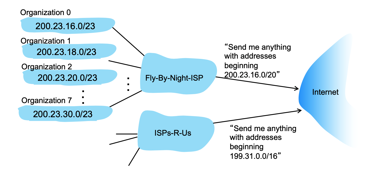
- Hierarchical Addressing (Route Aggregation): This hierarchical structure allows for highly efficient routing advertisements. Instead of telling the entire internet about every single organization's
/23network, the ISP aggregates the routes and simply advertises, "Send me anything with addresses beginning200.23.16.0/20".- The Problem: If the global Internet routers had to memorize the specific
/23subnet for every single small organization in the world, their routing tables (the maps they use to direct traffic) would be impossibly massive, slow, and expensive to maintain. - The Solution: Because an ISP distributes smaller chunks (like the eight subnets from
200.23.16.0/23to200.23.30.0/23) out of its own larger, contiguous master block, it can mathematically summarize them. - The Advertisement: The ISP (like the "Fly-By-Night-ISP" in the slide) tells the rest of the Internet routers, "Don't worry about memorizing these individual organizations. Just send me anything where the first 20 bits match
200.23.16.0/20". How about others like200.23.18.0/20? Even though the numbers16and18look different to us in decimal form, the Internet routers only look at the binary bits. When the ISP advertises200.23.16.0/20, it is telling the global routers to only check the first 20 bits of the address. If those 20 bits match, the packet goes to that ISP. As you can see from above image, the first 20 bits are completely identical (11001000 00010111 0001), because they are from the same ISP. - The Handoff: The global Internet now only has to remember one single routing rule instead of eight separate rules. When a data packet reaches the ISP's front door, the ISP's internal routers then look at the more specific
/23mask to deliver the packet to the correct organization's network.
- The Problem: If the global Internet routers had to memorize the specific
ICANN and Address Exhaustion
At the very top of the hierarchy, ISPs obtain their massive blocks of addresses from ICANN (Internet Corporation for Assigned Names and Numbers).
- ICANN's Role: ICANN allocates IP addresses globally through 5 regional registries (RRs), which then distribute them to local registries or ISPs. ICANN also manages the DNS root zone, including the delegation of Top-Level Domains (TLDs) like .com and .edu.
- Address Space Limits: The 32-bit architecture of IPv4 means there is a limited supply of addresses. ICANN allocated the very last chunk of available IPv4 addresses to the regional registries in 2011.
- Solutions: To combat IPv4 exhaustion, technologies like NAT (Network Address Translation) are used, while the long-term solution is transitioning to IPv6, which features a vastly larger 128-bit address space.
Network Address Translation (NAT)
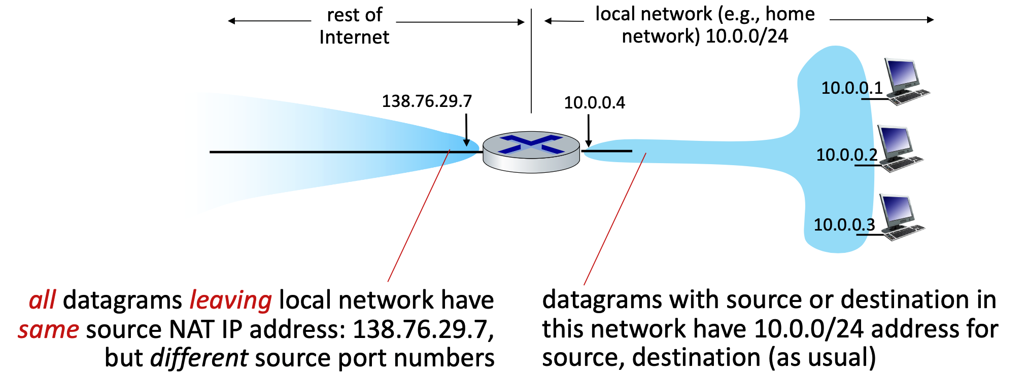
- Core Concept: NAT allows all devices within a local network to share a single, public IPv4 address when communicating with the outside Internet. Internally, these devices use "private" IP address spaces (such as
10/8,172.16/12, or192.168/16) that are not routable on the public internet. - Advantages: This approach requires only one public IP address from the ISP for the entire network. It also allows network administrators to change local addresses or switch ISPs without notifying the outside world, and it provides a layer of security because internal devices are not directly visible or addressable from the outside.
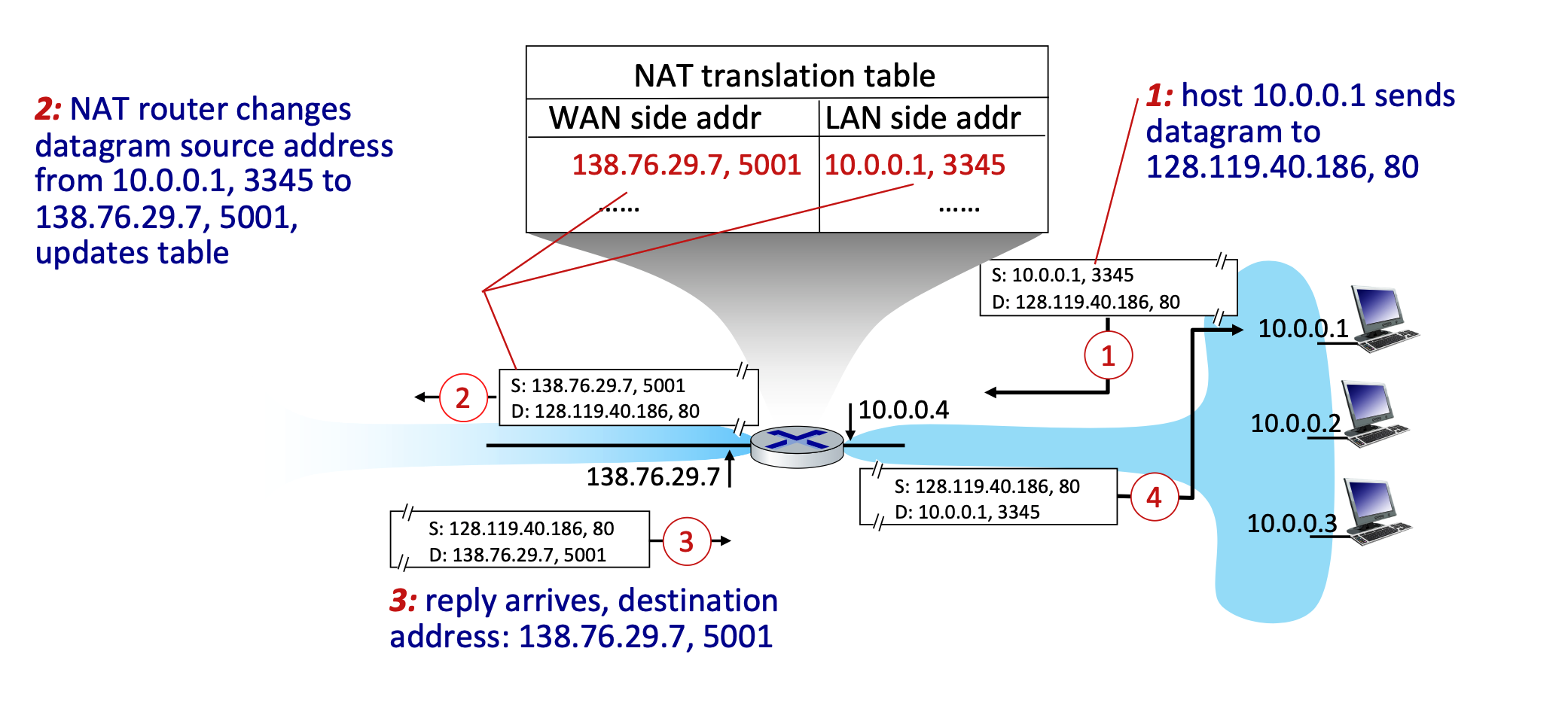
- How it Works (Implementation): The NAT router operates transparently by manipulating IP and port information:
- Outgoing Traffic: The router replaces the local source IP address and port number of every outgoing datagram with its own public NAT IP address and a newly generated port number. All outgoing packets share this same NAT IP but utilize different port numbers.
- The reason the NAT router must use different port numbers is purely for tracking and identification. Because all devices on the local network are forced to share the exact same public IP address to the outside world, the router needs a reliable way to tell their traffic apart when the replies come back from the Internet.
- Translation Table: The router remembers these mappings by creating a pair in its NAT translation table (e.g., mapping WAN side
138.76.29.7, 5001to LAN side10.0.0.1, 3345). - Incoming Traffic: When external replies arrive at the router's public IP and port, the router checks the table and rewrites the destination fields to match the original local device's IP and port.
- Outgoing Traffic: The router replaces the local source IP address and port number of every outgoing datagram with its own public NAT IP address and a newly generated port number. All outgoing packets share this same NAT IP but utilize different port numbers.
- Controversies: While NAT is extensively used in home, institutional, and 4G/5G networks, it has critics. Arguments against NAT state that routers should ideally only process up to Layer 3, and manipulating port numbers (Layer 4) violates the "end-to-end argument". Furthermore, NAT makes it difficult for outside clients to connect to servers hosted behind the NAT (a problem known as NAT traversal). Critics also argue the address shortage should simply be solved by adopting IPv6.
IPv6 Overview and Transition
- Motivation: The primary motivation for IPv6 was the complete allocation (exhaustion) of the 32-bit IPv4 address space. Secondary motivations include enabling different network-layer treatments for data "flows" and speeding up processing and forwarding with a fixed-length 40-byte header.
- Datagram Format: IPv6 features massive 128-bit addresses for both source and destination. It introduces new fields like a "flow label" and "priority" to manage data streams. To streamline router processing, IPv6 intentionally removes several IPv4 features: it has no checksum, it removes fragmentation/reassembly responsibilities from intermediate routers, and it moves "options" to an upper-layer next-header protocol.
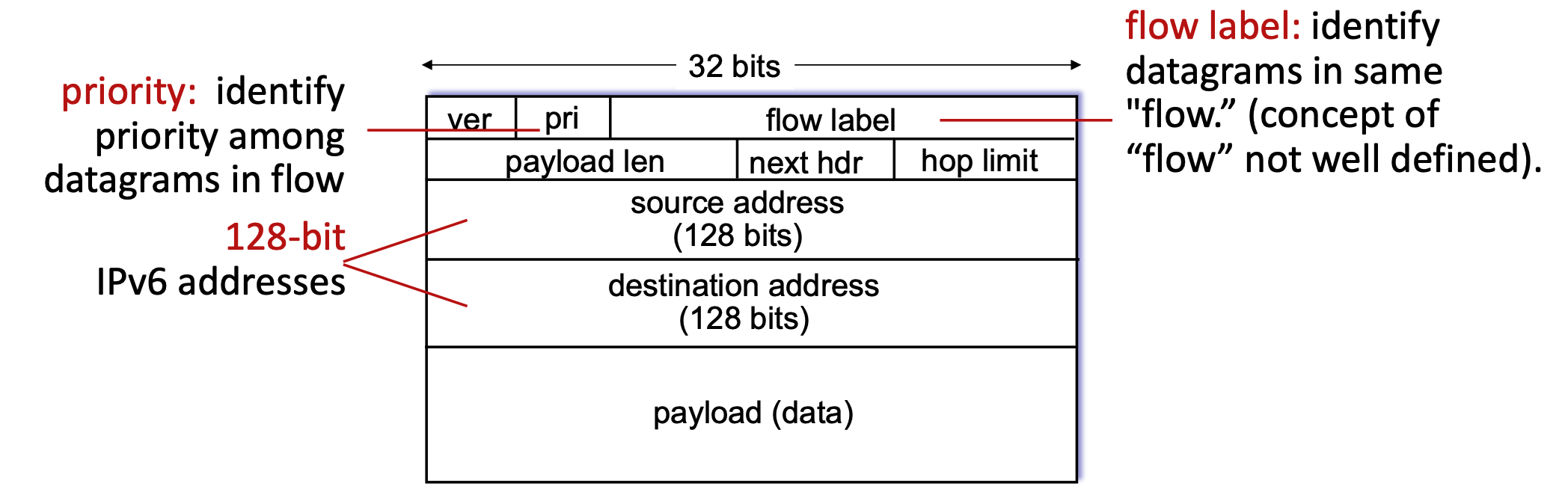
The "32 bits" label at the very top indicates the width of one single horizontal row in the diagram. In networking, these diagrams are traditionally drawn in chunks of 32-bit (4-byte) "words." However, because an IPv6 address is massively larger at 128 bits long, it physically cannot fit into a single 32-bit row. To accommodate this mathematically, the source address and destination address actually span four consecutive rows each (\(4×32\) bits = \(128\) bits).
- It’s purely visually for diagram convention!!! In practice, IPv6 address is just a continuous 128-bit field. No real concept of “rows” exists
Tunneling
-
Transitioning (Tunneling): Upgrading the entire internet to IPv6 simultaneously is impossible (no "flag days"), meaning IPv4 and IPv6 routers must coexist. To route IPv6 traffic across older IPv4 networks, a method called tunneling is used.
-
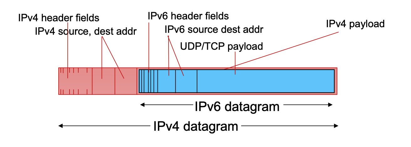
In tunneling, an entire IPv6 datagram is encapsulated and carried directly inside the payload field of an IPv4 datagram.
-
The IPv4 routers forward this "packet within a packet" until it reaches the next IPv6-capable router, which then extracts the original IPv6 datagram.
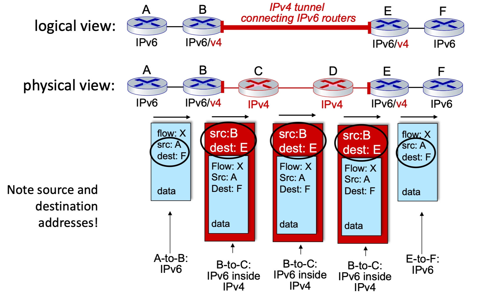
- The only time you need to encapsulate IPv6 inside IPv4 (tunneling) is when those two IPv6 routers are separated by an intervening network made up of older IPv4 routers. In that case, the IPv6 datagram is treated as "payload" so the older routers can carry it to the next IPv6-capable destination.
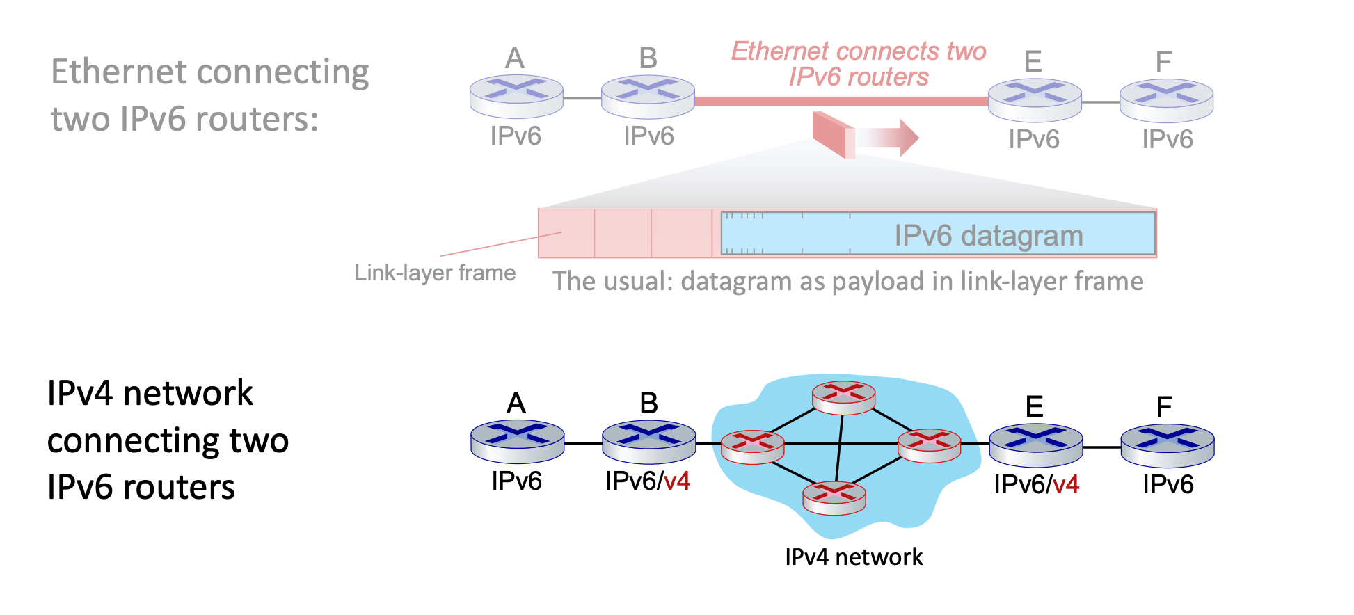
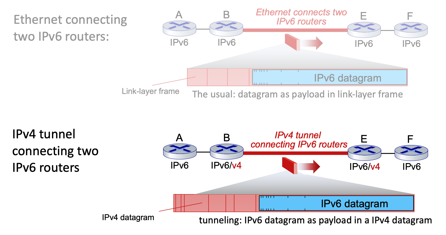
Top: IPv6 is payload of link-layer frame.
Bottom: IPv6 is payload of IPv4. IPv4 is payload of link-layer frame.
-
-
The Concept: An IPv6 packet is encapsulated within the payload of an IPv4 packet. To the IPv4 routers in the middle, the packet looks like standard IPv4 traffic.
- The Process:
- Entry Node (Router B): Receives an IPv6 packet, realizes the next hop is IPv4-only, and adds an IPv4 header. The source is B, and the destination is E.
- Router B addresses the outer IPv4 packet to Router E because Router E is the first device on the other side of that "ocean" that is capable of understanding IPv6 again.
- The Tunnel (Routers C & D): These routers only see the IPv4 header and route the packet normally.
- Exit Node (Router E): Receives the IPv4 packet, strips the IPv4 header, and forwards the original IPv6 packet to the final destination.
- Entry Node (Router B): Receives an IPv6 packet, realizes the next hop is IPv4-only, and adds an IPv4 header. The source is B, and the destination is E.
- Logical vs. Physical: Logically, it appears as a direct IPv6 connection between routers B and E. Physically, it is a series of IPv4 hops.
IPv6 Adoption Trends
The transition from IPv4 to IPv6 is a long-term evolution of the internet's fundamental layer, characterized by steady but gradual global growth.
Adoption Statistics
- Google Traffic: As of 2020, approximately 30% of clients access Google services via native IPv6.
- Government Sector: About 1/3 of all US government domains are currently IPv6 capable according to NIST.
- Growth Pattern: Adoption was nearly non-existent for the first 15 years, with a significant "inflection point" around 2012 leading to the current steady upward trend.
Deployment Challenges
- Timeframe: The transition has been ongoing for over 25 years. This is considered an exceptionally long deployment cycle in the tech industry.
- Comparison: In the time it has taken to reach 30% IPv6 adoption, entire industries like social media, streaming video, and cloud gaming have been born and reached maturity.
- The "Why" Factor: Unlike application-layer updates (like a new version of a browser), IPv6 requires updating the "plumbing" of the internet, which involves hardware replacement and complex coordination across millions of independent networks.
Generalized Forwarding, SDN
Generalized Forwarding and Match-Plus-Action
Core Abstraction: Match-Plus-Action
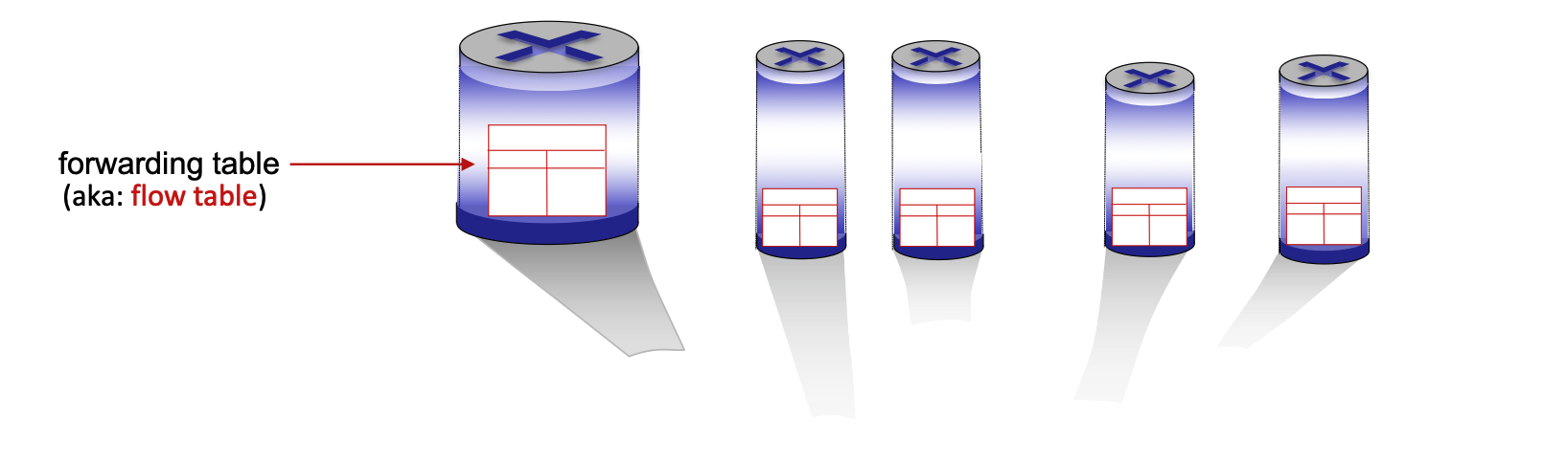
Generalized forwarding shifts from traditional destination-based forwarding to a more flexible "match-plus-action" model. Each router contains a forwarding table (also known as a flow table). The router matches specific bits in an arriving packet’s headers and executes a corresponding action.
- Destination-based Forwarding: Traditional method; forwards based solely on the destination IP address.
- Generalized Forwarding: Many header fields can determine the action. Possible actions include drop, copy, modify, or log the packet.
Flow Table Components
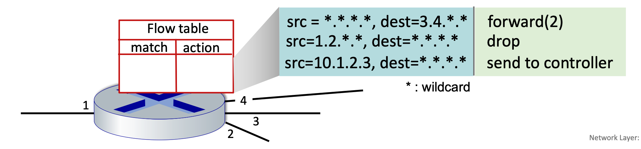
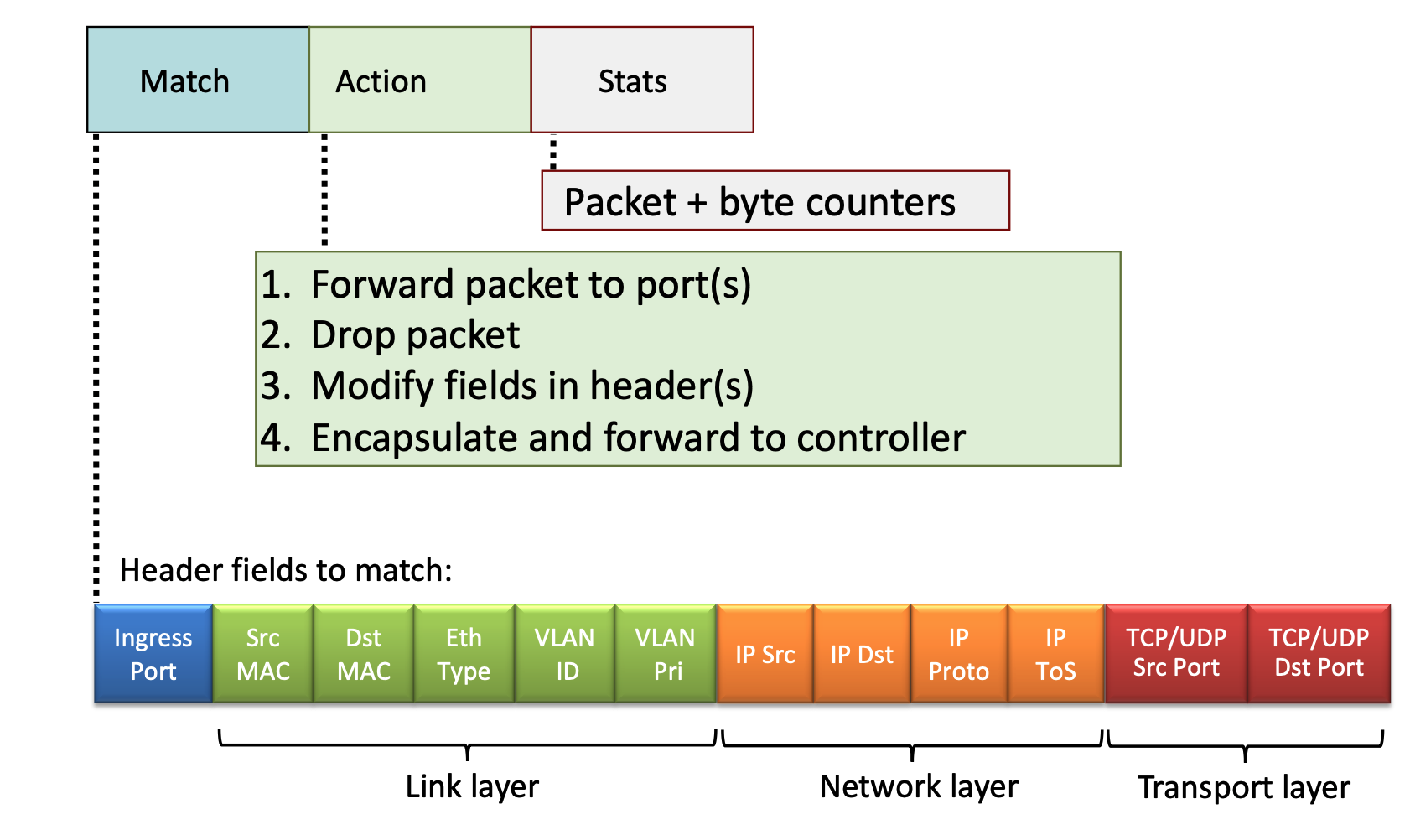
A flow table entry consists of several key parts to handle packet processing:
- Match: A pattern values matched against packet header fields (Link, Network, or Transport layers).
- Actions: For a matched packet, the router can drop, forward, modify, or send the packet to the controller.
- Priority: Used to disambiguate between overlapping patterns.
- Counters: Statistics including the number of bytes and number of packets processed.
OpenFlow Implementation
OpenFlow is a standard communication protocol that acts as the "language" between a central network controller (the brain) and the switches (the muscles) in a Software-Defined Network (SDN).
OpenFlow defines exactly how these two pieces talk to each other over a secure channel:
- Packet Arrival: A packet enters a switch.
- The Match: The switch looks at its table. "Does this packet match any rule (IP, MAC, or Port)?"
- The Action:
- If it matches: The switch does what the rule says (Forward, Drop, or Modify).
- If it's a "Miss": The switch sends the packet (or a summary) to the Controller and asks, "I've never seen this before, what do I do?"
- The Update: The Controller decides the path, sends a new rule down to the switch, and the switch handles all future identical packets at hardware speed.
Header Fields for Matching
OpenFlow allows matching across multiple layers of the protocol stack:
- Link Layer: Ingress port, Source/Destination MAC addresses, Ethernet Type, VLAN ID, and VLAN Priority.
- An ingress port is simply the physical or logical port on a switch or router where a packet enters the device.
- Network Layer: Source/Destination IP addresses, IP Protocol, and IP Type of Service (ToS).
- Transport Layer: TCP/UDP Source and Destination Ports.
Unifying Network Devices
The match-plus-action abstraction unifies different kinds of devices into a single framework:
- Router: Match longest destination IP prefix; Action: forward out a link.
- Switch: Match destination MAC address; Action: forward or flood.
- While forwarding is a surgical, 1-to-1 mapping (Port A → Port B), flooding is a 1-to-many mapping (Port A → All other Ports).
- Firewall: Match IP addresses and TCP/UDP port numbers; Action: permit or deny.
- NAT: Match IP address and port; Action: rewrite address and port.
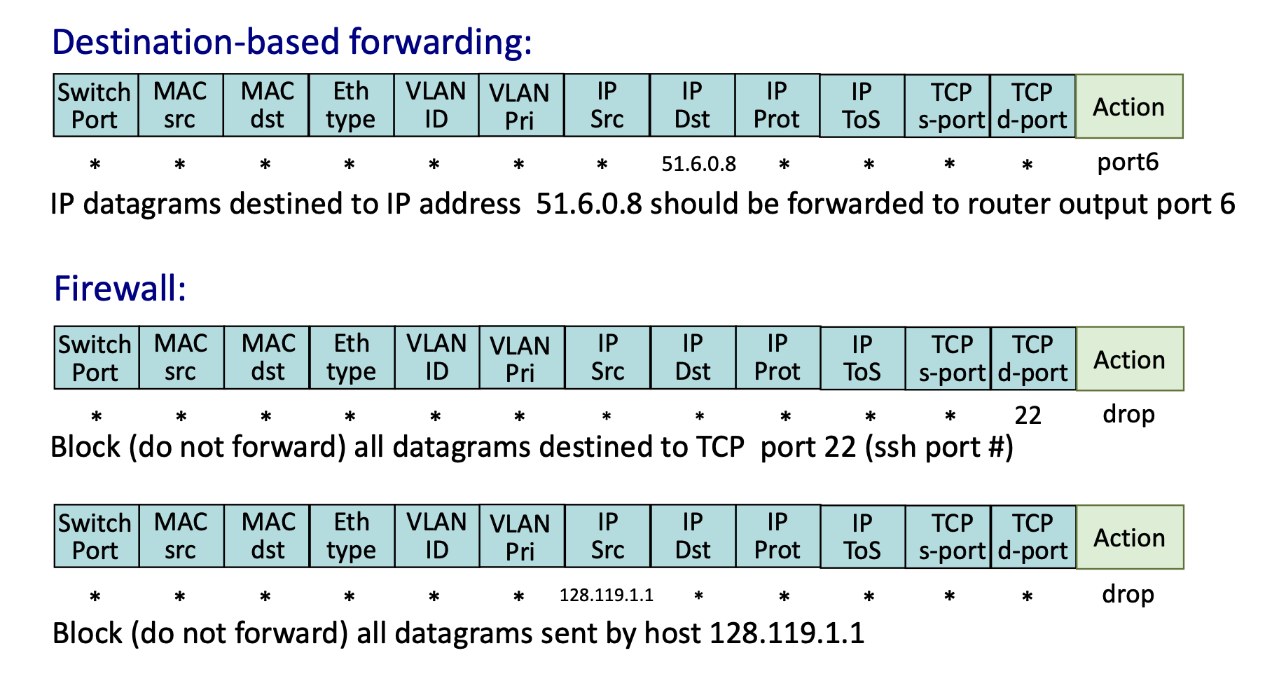
Practical OpenFlow Examples
- Destination-based Forwarding: Match
IP Dst = 51.6.0.8; Action:forward(port6). - Firewall (Port Blocking): Match
TCP d-port = 22(SSH); Action:drop. - Firewall (Host Blocking): Match
IP Src = 128.119.1.1; Action:drop.
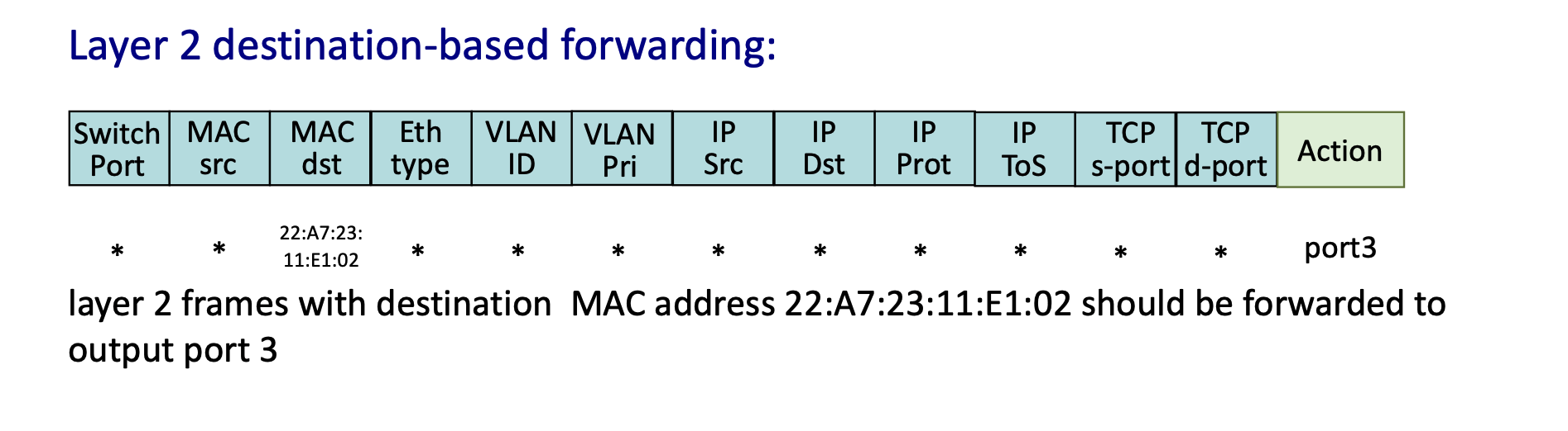
- Layer 2 Forwarding: Match specific
MAC dstaddress; Action:forward(port3).
Network-Wide Behavior and Programmability
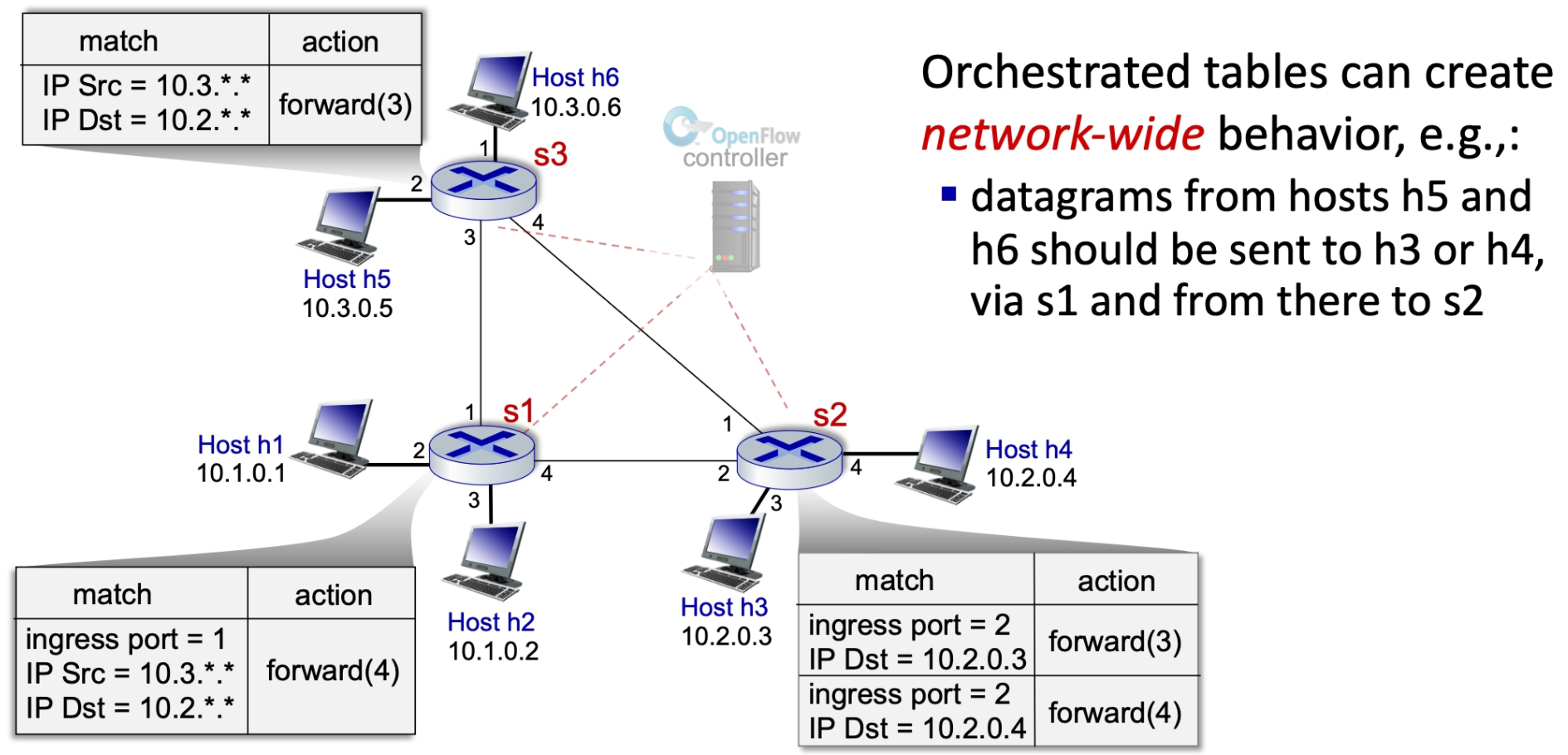
Orchestrated Tables
Orchestrated tables create network-wide behavior. For example, a controller can program specific paths so that datagrams from certain hosts (like h5 and h6) are sent to specific destinations (like h3 or h4) via a specific sequence of switches (s1 to s2), regardless of standard routing protocols.
Summary of Generalized Forwarding
- Match Plus Action: Matches bits in arriving packet headers at any layer and takes a local action (drop, forward, modify, or send to controller).
- Matching over many fields (link-, network-, transport-layer)
- Network Programmability: Provides a simple form of "network programmability" with per-packet processing.
- Historical and Future Context: Has roots in active networking; today, it has evolved into more generalized programming like P4.
- P4 = a programming language to define how network devices process packets
The Controversy of Layer Violations in Generalized Forwarding
The Conflict: Breaking the OSI Model
Traditionally, routers are Layer 3 (Network) devices that should only process IP addresses. Generalized Forwarding breaks this "modular" rule by inspecting Layer 4 (Transport) data like TCP/UDP port numbers.
Why It’s Controversial (The "Cons")
- Performance Hits: Routers are optimized for IP prefixes. Inspecting deeper headers (Layer 4) adds complexity and can slow down hardware (ASICs).
- ASIC (Application-Specific Integrated Circuit) is the specialized hardware "brain" inside a router or switch.
- End-to-End Principle: Purists believe the "middle" of the network should be "dumb" (just moving packets), while intelligence stays at the endpoints (computers).
Why We Use It Anyway (The "Pros")
By ignoring layer boundaries, a single device becomes a Universal Forwarding Element, handling tasks that used to require separate, expensive hardware:
- Security: Acts as a firewall by dropping specific traffic (e.g., blocking Port 22 for SSH).
- Load Balancing: Redirects traffic based on application type (e.g., sending Web traffic vs. Email traffic to different servers).
- It can see that a packet is "Web Traffic" (Port 80/443) and send it to a server farm, while sending "Email Traffic" (Port 25) somewhere else.
- Quality of Service (QoS): Prioritizes time-sensitive data (video streaming) over background tasks (downloads) to prevent lagging.
The Unification Argument
This "layer violation" allows for the merging of several distinct devices into one:
- Router: Matches IP prefix.
- Switch: Matches MAC address.
- Firewall: Matches IP + Port.
- NAT: Rewrites IP + Port.
The Mailman Analogy: A traditional router is like a mailman who only looks at the address on the envelope. A "layer violation" is like that mailman opening the envelope to see if it’s a bill or a birthday card before deciding how fast to deliver it. It breaks the rules of privacy/layers, but makes the system much more programmable.