Distributed System Architectures & Models
System Architecture
What is “System Architecture”?
System architecture defines how a system is structured. This involves three things:
- Identify components: what pieces make up the system (clients, servers, middleware, data, etc.).
- Define functions of each component: what each part is responsible for.
- Define relationships and interactions: how components communicate and depend on each other.
Think of this as the “blueprint” of a distributed system.
Architectural Styles (Big Idea)
Core idea
First, organize the system into logically different components, then decide how to distribute those components across machines.
Two main styles shown:
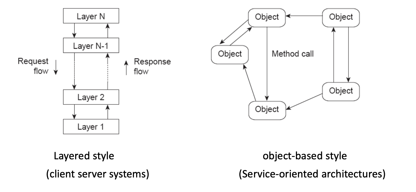
Layered Style (typical in client-server systems)
- You have stacked layers: Layer 1 → Layer 2 → ... → Layer N.
- Requests flow down through layers.
- Responses flow up through layers.
Typical meaning:
- Each layer provides services to the layer above it.
- Each layer hides details from higher layers.
- Changes in one layer ideally don’t break others.
Example intuition:
- Application → Middleware → Network → OS
Object-based Style (typical in service-oriented architectures)
- System is composed of objects/services that directly call each other.
- There is no strict top-to-bottom layering.
- Objects interact via method calls / messages.
This is closer to:
- Microservices
- RPC-based systems
- Distributed object systems
Layers in a Distributed System
Three conceptual layers:
Platform (bottom layer)
- Provides fundamental services:
- Communication (networking)
- Resource management (CPU, memory, storage)
- Usually handled by the OS and network stack.
- Applications typically don’t deal with this directly.
Middleware (middle layer)
- Sits between platform and applications.
- Hides heterogeneity (different machines, networks, OSes).
- Provides an “easier” API for distributed programming.
- Example: RPC (Remote Procedure Call), message queues, etc.
Applications (top layer)
- Actual distributed applications and services:
- FTP
- Web services
- Cloud applications
System Architectures
Three major types are discussed:
Client-Server Architecture
Variants:
- Multiple clients / single server
- Multiple clients / multiple servers
- Mobile clients
- Thin clients (minimal local processing)
Basic idea:
- Clients send requests.
- Server processes and returns results.
Client-Server Timing:
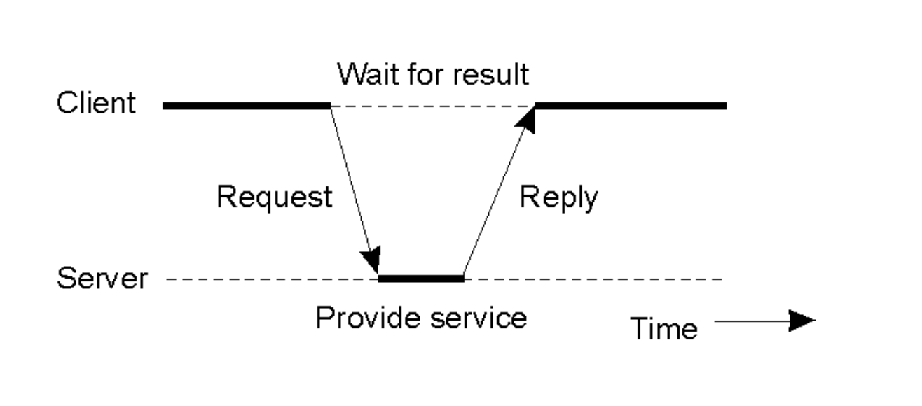
- Client sends a request.
- Server processes (“Provide service”).
- Client waits.
- Server replies.
Multiple-Client / Single-Server
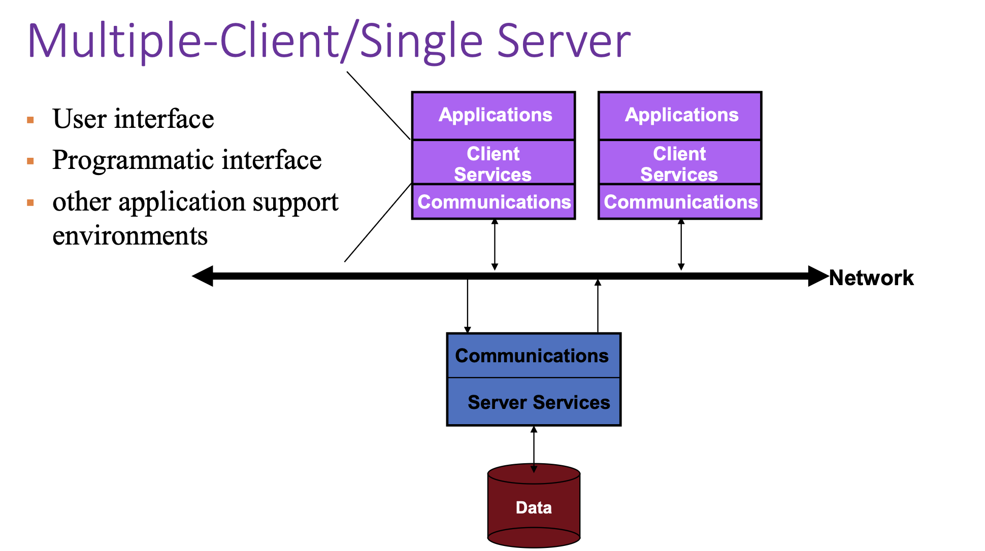
Key issues:
- Server becomes a bottleneck (limits performance).
- Single point of failure (if server crashes, system fails).
- Hard to scale (adding more clients overloads the server).
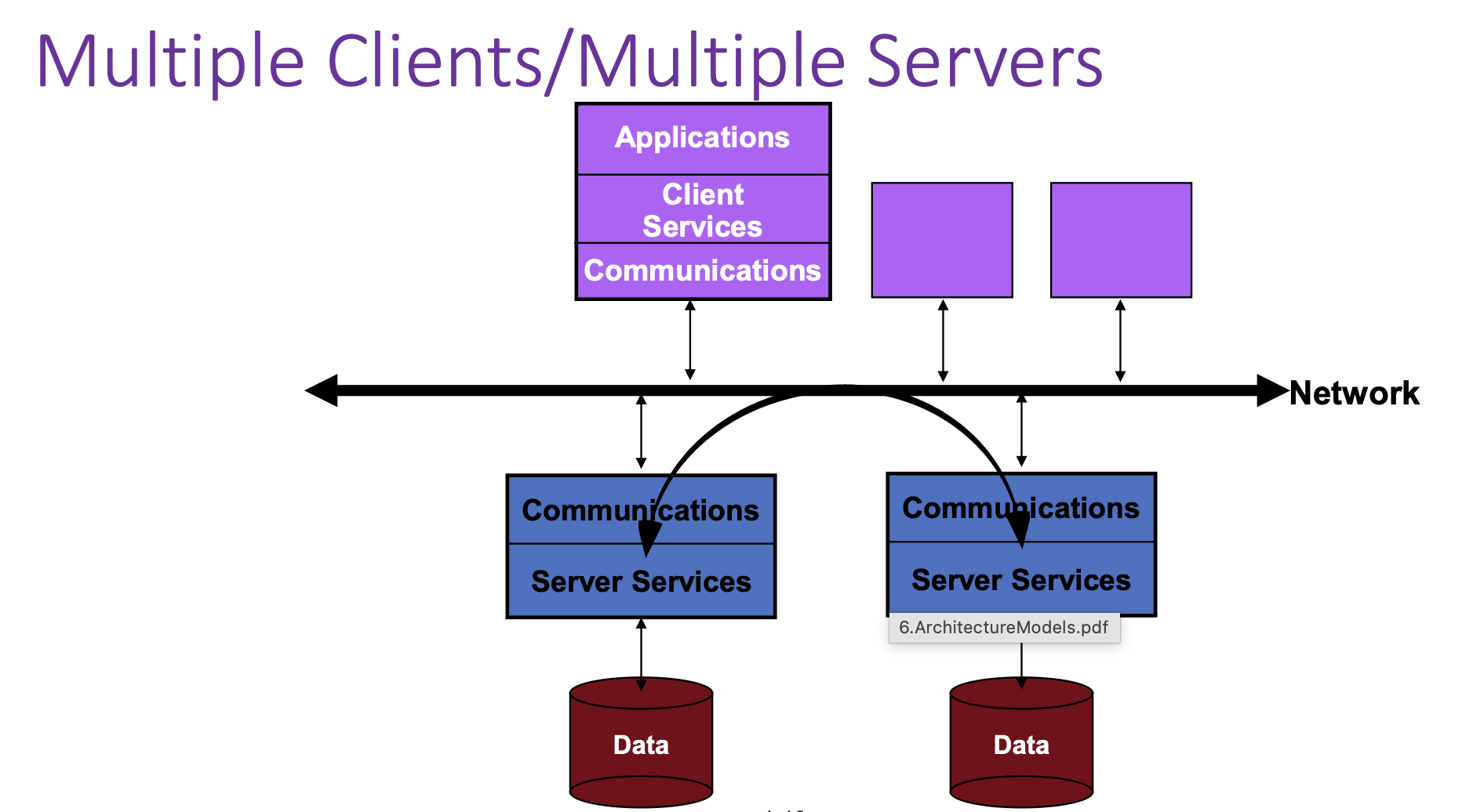
Multiple Clients / Multiple Servers
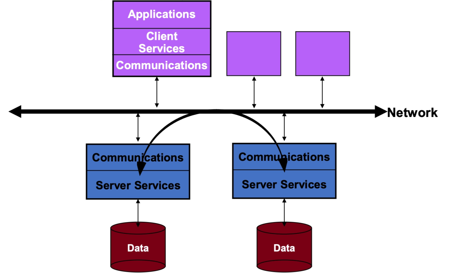
- Clients connect to a network.
- Multiple servers exist, each with its own data store.
- Clients can talk to different servers.
- This improves:
- Scalability
- Fault tolerance
- Load distribution
This is closer to modern cloud systems.
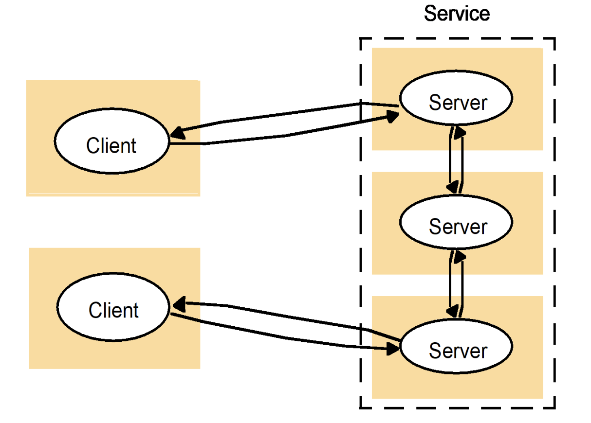
A Service Across Multiple Servers
This is a subset (refinement) of Multiple Clients / Multiple Servers, which is something more specific.
- A single logical “service” may be implemented by multiple physical servers.
- A client might:
- Talk to one server.
- That server may communicate with other servers to fulfill the request.
This represents:
- Load balancing
- Replication
- Distributed backends
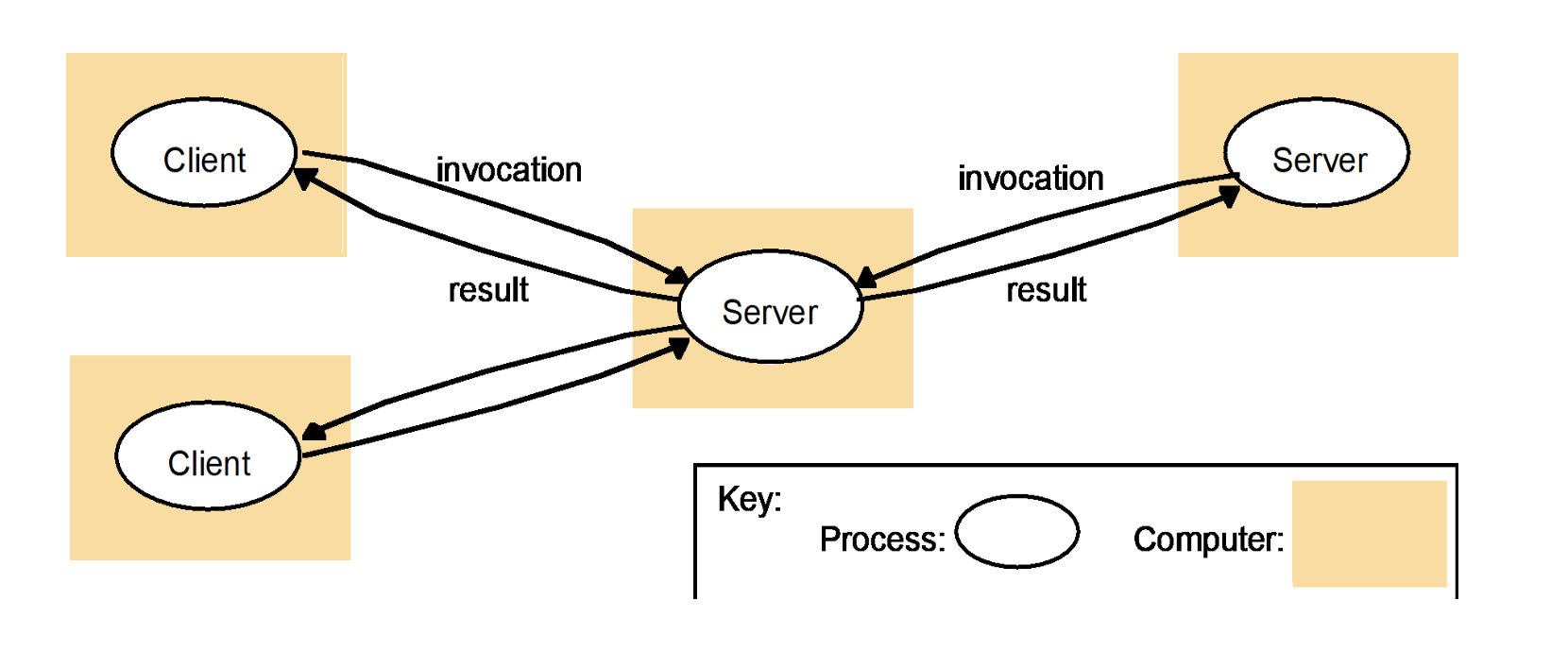
Multiple-Client / Multiple-Server Communication
This is a specific way of realizing “A Service Across Multiple Servers.”
- Multiple clients send requests to a middle server.
- That server then invokes other backend servers.
- Results propagate back to clients.
Key point:
- There is often an intermediate service (gateway, coordinator, or API server).
- This is common in:
- Microservices
- Distributed databases
- Cloud applications
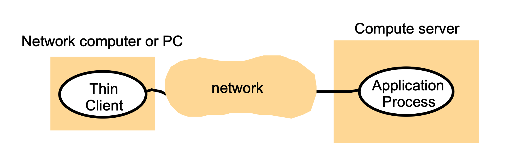
“Thin Clients”
What is a thin client?
- A thin client runs only the user interface (GUI) locally.
- The actual application logic and computation run on a remote compute server.
Key characteristics
- Client does minimal processing.
- Most work (computation, storage, application execution) happens on the server.
- Client mainly sends user inputs and displays results.
Examples (historical / real-world)
- X11 systems (graphics rendered remotely).
- Early devices like Palm Pilots.
- Conceptually similar to modern remote desktops or cloud apps.
Big idea
- Good when clients are weak (low power, mobile, or limited hardware).
- Shifts complexity and cost to centralized servers.
Multitier Systems
Overall idea
- Organize a complex system into three logical layers:
- User-interface level
- Processing level
- Data level
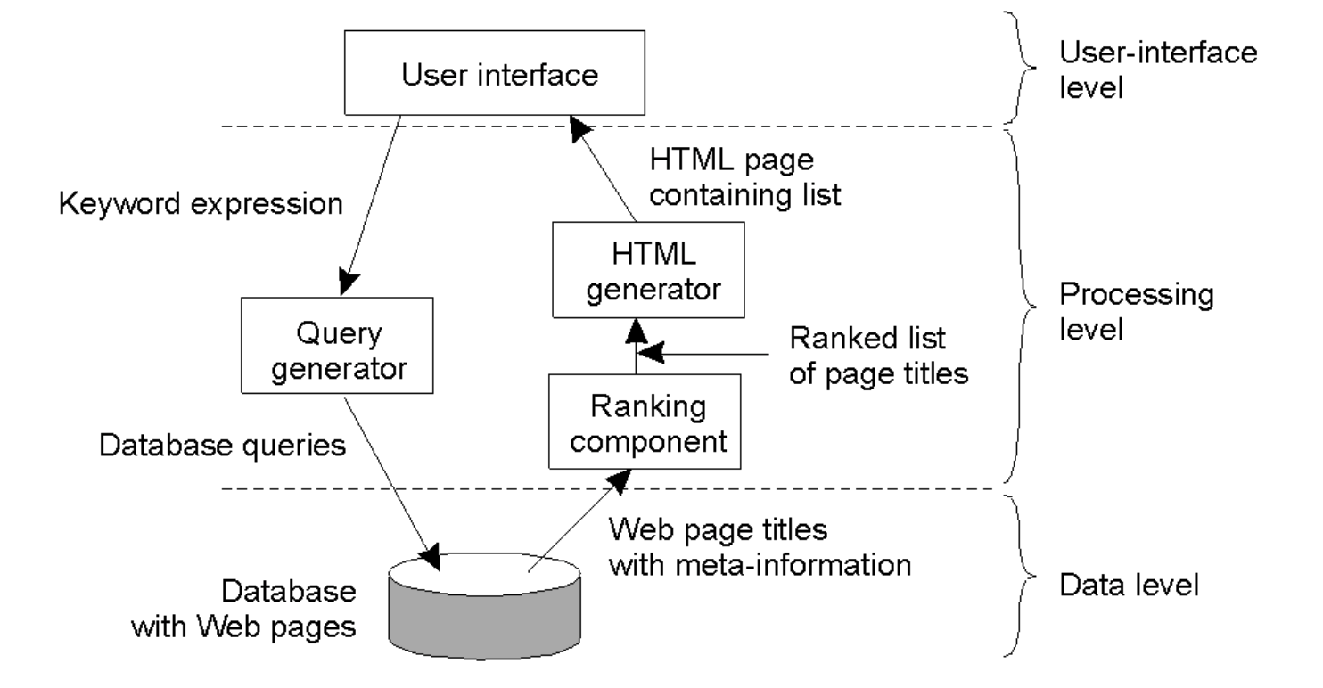
Search Engine Example
(a) User-interface level (top)
What the user sees and interacts with:
- User enters a keyword expression (search query).
- System returns an HTML page containing a ranked list of results.
Components here:
- “User interface” (e.g., web page or browser front end).
(b) Processing level (middle)
This is where most logic happens:
- Query generator
- Takes the user’s keywords.
- Translates them into database queries.
- Ranking component
- Receives page titles + metadata from the database.
- Ranks results (e.g., relevance, popularity).
- HTML generator
- Takes ranked results.
- Formats them into an HTML results page for the user.
Flow: User query → Query generator → Database
Database → Ranking component → HTML generator → User
(c) Data level (bottom)
- A database containing:
- Web pages
- Page titles
- Metadata (keywords, links, etc.)
This is the persistent storage layer that supports the search engine.
Multitier Architectures
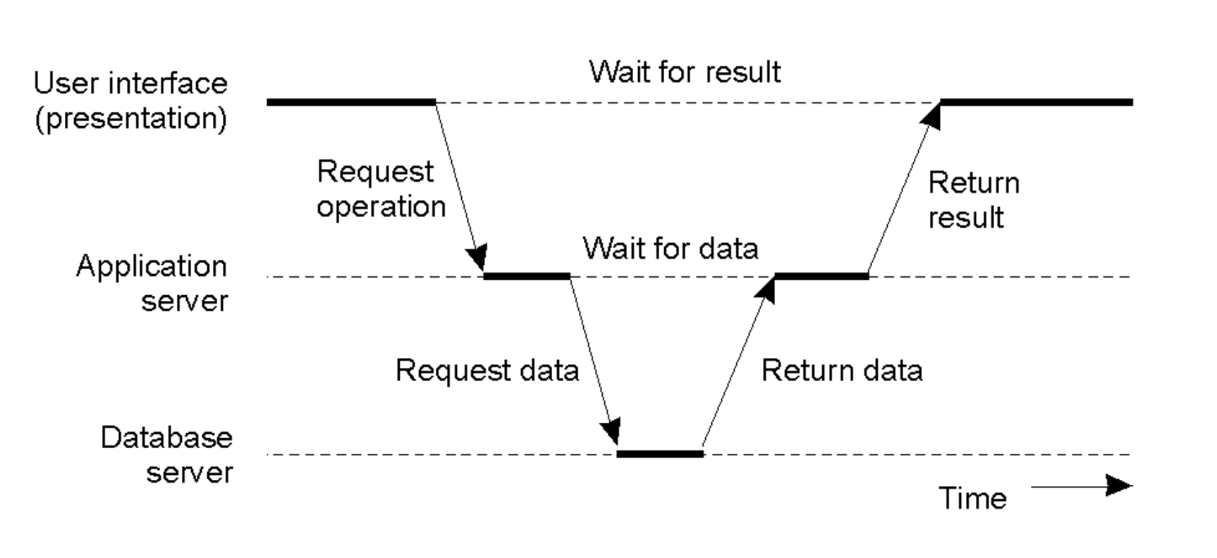
Server as Client
- In complex systems, a server often acts as a client to other services.
- The Flow: User Interface \(\rightarrow\) Request Operation \(\rightarrow\) Application Server \(\rightarrow\) Request Data \(\rightarrow\) Database Server. The result flows back up the chain.
- Latency Cost: This introduces multiple "Wait for data" and "Wait for result" steps, increasing total response time.
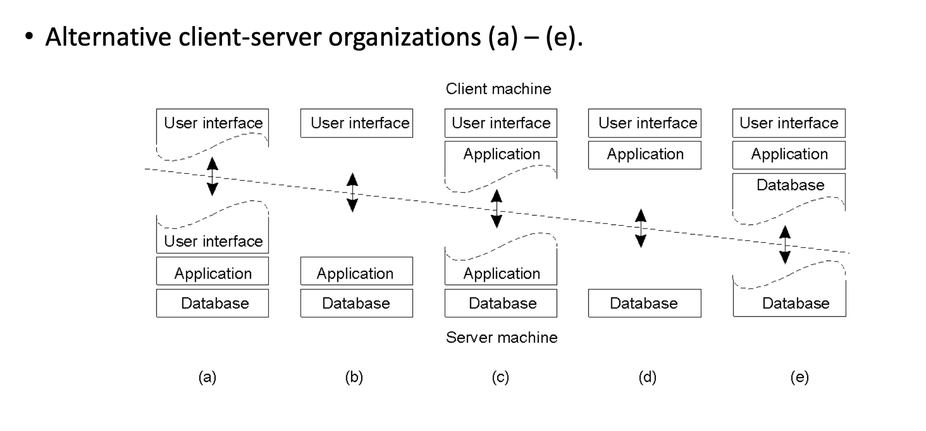
Client-Server Organization Models
The architecture can be split in various ways between the Client Machine and Server Machine:
- Thin Client: Only the User Interface is on the client; Application and Database are on the server (Models d, e).
- Fat Client: User Interface and part/all of the Application logic are on the client (Models a, b, c).
Peer-to-Peer (P2P) Systems
- Design: A decentralized network where applications communicate directly with each other without a central server.
- Structure: Each node contains both the Application logic and Coordination code to manage the network connections.
Design Requirements
Architects must balance three core pillars:
- Performance: Metrics, scalability, load balancing, and caching.
- Dependability: Reliability and fault tolerance.
- Security.
Performance Principles
Metrics
- Response Time: Total time from request to result. While the average is useful, systems must optimize for Tail Latency (outliers).
- Throughput: Number of jobs completed per unit of time.
- System Utilization: How busy the resources are.
The Bottlenecks
- Network: Message exchange is physically slow (~1 msec RTT on LAN) due to protocol overhead.
- Storage: Disk access is typically slow.
Guiding Principles for Scaling
- Granularity: Avoid "Fine-grained parallelism" (small computations with high interaction) as the communication overhead creates trouble. Prefer "Coarse-grained" (large computations, little data transfer).
- Avoid Centralization: Centralized components, tables, or algorithms become bottlenecks at scale (e.g., a single mail server for everyone).
- Scale Well: A solution that works for 200 machines often fails miserably for 2,000,000.
- Caching & Replication: Essential tools for improving both performance and dependability.
Dependability & Availability
Definitions
- Reliability: The ability of a system to run continuously without failure.
- Availability: The probability that the system is operational at any given time \(t\).
Measuring & Improving Availability
- Uptime Formula: \((MTBF - MTTR) / MTBF\)
- MTBF: Mean Time Between Failures. This is the average time the system runs smoothly before something breaks.
- MTTR: Mean Time To Repair. This is the average time it takes to get the system back up after a crash.
- Strategy: To improve availability, you must either increase the time between failures (MTBF) or reduce the time it takes to fix them (MTTR).
- Breakdown of Repair Time (MTTR): Detection time + Diagnosis time + Fix time.
Failure Models
Systems fail in three distinct ways:
- Fail-stop / Fail-restart: The component simply stops working (crashes) or reboots.
- Byzantine Failure: The component continues running but sends arbitrary or malicious data.
- Limping: The component works but is extremely slow.
Hardware Failure Lifecycle (The Bathtub Curve)
Hardware failure rates change over time:
- Infant Mortality: High failure rate initially due to manufacturing defects ("Decreasing Failure Rate").
- Constant Failure Rate: A period of stability where failures are low and random during the product's useful life.
- Wear Out: The failure rate increases again as components age and degrade ("Increasing Failure Rate").
- Observed Failure Rate (The Bathtub Curve): The total failure rate observed is the sum of these three curves, creating the characteristic "Bathtub" shape (High \(\rightarrow\) Low/Flat \(\rightarrow\) High).
Redundancy & Fault Tolerance
How to Improve Dependability???
Hardware Redundancy (Masking)
- Concept: Use multiple components so that if one fails, others take over.
- The Math of Redundancy: If one server has a 0.05 chance of failure (95% uptime), 4 redundant servers have a \(0.05^4 = 0.000006\) chance of simultaneous failure. This boosts reliability from 95% to 99.9994% (1 - 0.0006%).
- Types: Spare/standby computers, replicated servers, or redundant network routes.
Software Redundancy
- Process Redundancy: Maintaining standby processes to take over computation.
- Data Redundancy: Replicating data or using transaction rollbacks.
- Challenge: Keeping replicated data consistent (updating all copies) is difficult.
Design for Fault Tolerance
- Decompose systems into isolated modules to limit shared state.
- Fail-Fast: Modules should operate correctly or crash immediately (don't send bad data).
- Heartbeats/Watchdogs: Mechanisms to detect failure quickly.
- Self-Tuning: Reduce configuration errors (a major source of downtime).
- Redundancy: Implement redundancy across hardware, software, and data layers.
- Transactions: Use sessions or a transactions mechanism to ensure data integrity during failures.
Security
- Distributed Challenges: Security is harder because communication channels and resources are distributed and exposed to the network.
- Key Threats: Process attacks, Channel interception, Denial of Service (DoS).
- Core Issues: Privacy, Authentication, Availability, and Integrity.
Tail Latency
- Definition: Tail latency refers to the high-percentile response times (such as the 99th or 99.9th percentile) that are significantly slower than the average or median.
- The "Tail" Concept: If you plot all request times on a histogram, most cluster around a fast average, but a few "outliers" stretch far to the right, forming a long, thin "tail" on the graph.
- The Outliers: While the median (P50) might be 10 ms, the tail (P99) could be 200 ms or more due to rare events like background system tasks, network congestion, or hardware hiccups.
- A "Bad Luck" Event: It represents the experience of the unluckiest users who hit a momentary bottleneck that most other users avoided.
- The Multiplier Effect: In distributed systems, a single user request often triggers sub-calls to hundreds of servers; if just one of those back-end servers hits its "tail," the entire user experience is delayed, making a slow response much more likely for the user than for an individual server.
- User Retention and Revenue: High tail latency feels like "lag" or "jank" to a user; even if the system is fast 99% of the time, that 1% of slow requests can frustrate power users, leading to lower engagement and lost revenue for high-scale platforms.
The CDF (The "Percentile" View)
The x-axis is still Latency, but the y-axis is the Percentage of total requests.
- At the 50% mark on the y-axis, you look down to the x-axis to find your P50.
- At the 99% mark on the y-axis, you look down to find your P99.
- This graph is great because it clearly shows how "long" the tail is. If the line stays flat for a long time before hitting 100%, you have a serious tail latency problem.